Rethinking The 3G Conversion Pages/Process
Re: Rethinking The 3G Conversion Pages/Process
|
Administrator
|
Oh, I should have said it also has several fuse positions left that could be used for other accessories. And the factory fuse box is still in use.
Gary, AKA "Gary fellow": Profile
Dad's: '81 F150 Ranger XLT 4x4: Down for restomod: Full-roller "stroked 351M" w/Trick Flow heads & intake, EEC-V SEFI/E4OD/3.50 gears w/Kevlar clutches
|
|
I've seen your posts about your fuse box mod. I don't think I currently have the patience for that.
Ignore my earlier question about a common ground. I think I over thought that a bit.
Will
-- 1982 F-250 HD 4x4 400/C6 4.10 Dana61 (Borgeson/Bluetop/Lee, 3G) |
Re: Rethinking The 3G Conversion Pages/Process
|
Administrator
|
I have a cheap and dirty Chinese little fuse/relay panel where my starter relay used to live.
It houses fuses and relays for my PMGR, high beams, low beams, fog lights, horn and ..... I'm having a brainfart.  I also have a relay (Ford kit) for my blower motor. My Megafuse holder is mounted to the side of it. There are pictures here on the forum (somewhere)
Jim,
Lil'Red is a '87 F250 HD, 4.10's, 1356 4x4, Zf-5, 3G, PMGR, Saginaw PS, desmogged with a Holley 80508 and Performer intake. Too much other stuff to mention. |
Re: Rethinking The 3G Conversion Pages/Process
|
In reply to this post by Gary Lewis
Just answered Gary! 
Jeff / 1984 F350 Crew Cab 4x4/5.8L w351 4V/ T18/ D50 4.10 front/ 8' bed.
Restored 2019-2022. Nicknamed «Big Brother 1984», due to its soooo-looong shape & nod to George Orwell's 1984 famous novel. |
Re: Rethinking The 3G Conversion Pages/Process
|
Administrator
|
Will - If I had it to do over again I'd go with an aftermarket fuse and relay panel. These Ford units are not easy to use. But from what both Jim and Scott have said the aftermarket ones are.
Jeff - I replied to you. We are on!
Gary, AKA "Gary fellow": Profile
Dad's: '81 F150 Ranger XLT 4x4: Down for restomod: Full-roller "stroked 351M" w/Trick Flow heads & intake, EEC-V SEFI/E4OD/3.50 gears w/Kevlar clutches
|
Re: Rethinking The 3G Conversion Pages/Process
|
Administrator
|
I've re-drawn the schematic for the Done Right solution, as shown below. I've done my best on the wire colors, but it isn't all that good.
 Anyway, please check it over as I'm about to start creating that harness. 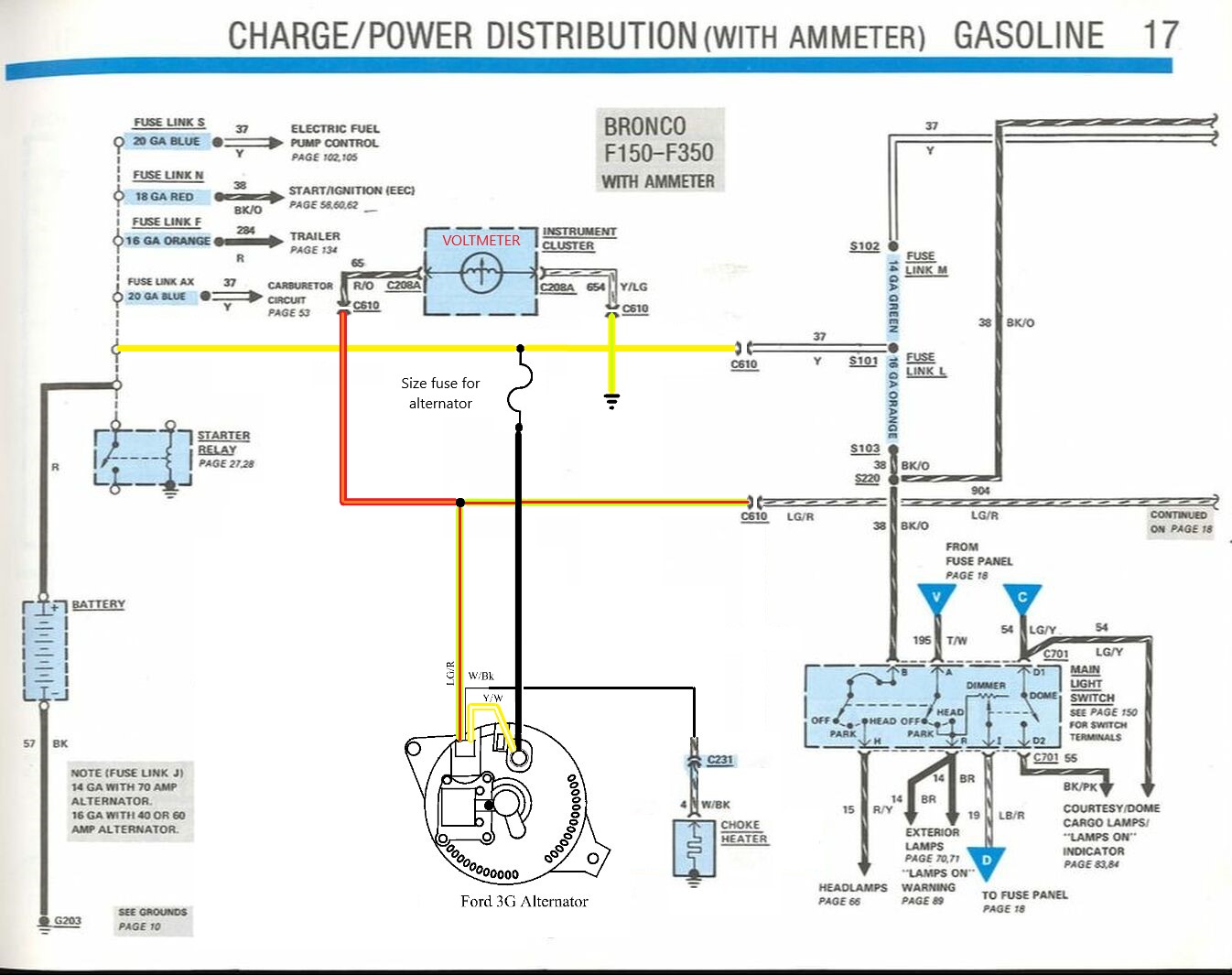
Gary, AKA "Gary fellow": Profile
Dad's: '81 F150 Ranger XLT 4x4: Down for restomod: Full-roller "stroked 351M" w/Trick Flow heads & intake, EEC-V SEFI/E4OD/3.50 gears w/Kevlar clutches
|
|
Just to be clear, do the R/O and the Y/LG wires for the Voltmeter connect to the Yellow wire on the C610?
Will
-- 1982 F-250 HD 4x4 400/C6 4.10 Dana61 (Borgeson/Bluetop/Lee, 3G) |
Re: Rethinking The 3G Conversion Pages/Process
|
Administrator
|
No, and that's a good question. Is this better?
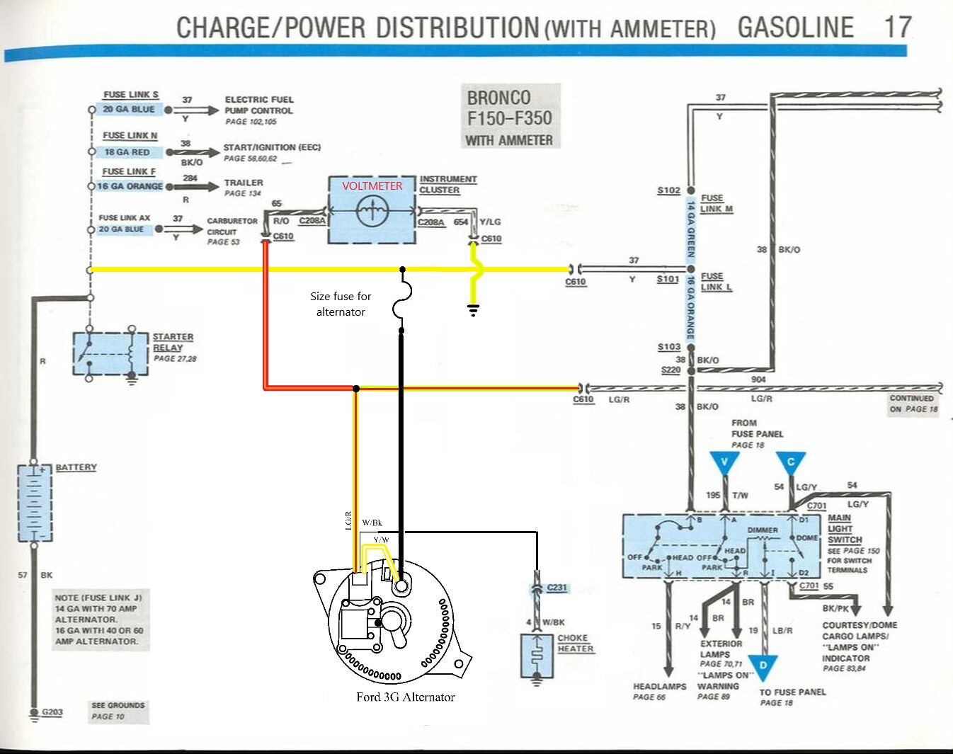
Gary, AKA "Gary fellow": Profile
Dad's: '81 F150 Ranger XLT 4x4: Down for restomod: Full-roller "stroked 351M" w/Trick Flow heads & intake, EEC-V SEFI/E4OD/3.50 gears w/Kevlar clutches
|
Re: Rethinking The 3G Conversion Pages/Process
|
Administrator
|
I would put the Megafuse to the relay terminal and run an entirely independent Y-37
Or perhaps your schematic is not really proportional and the HMEG is close to the relay and you have an eyelet on 37 at the fused side, and an eyelet jumper from the same, to the relay? Id like to see whatever termination noted if there isn't (C-123) To be clear, you don't show a splice (S-123) but you really don't give any information on that 3-way connection 
Jim,
Lil'Red is a '87 F250 HD, 4.10's, 1356 4x4, Zf-5, 3G, PMGR, Saginaw PS, desmogged with a Holley 80508 and Performer intake. Too much other stuff to mention. |
|
In reply to this post by Gary Lewis
Yes, that makes it more clear on the Y/LG for the Voltmeter. Should these two areas be the same or are they actually making a connection here:
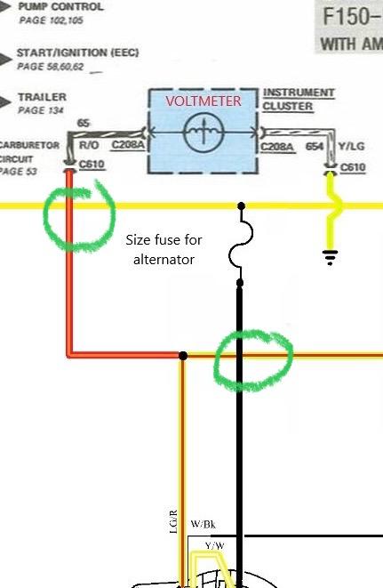
Will
-- 1982 F-250 HD 4x4 400/C6 4.10 Dana61 (Borgeson/Bluetop/Lee, 3G) |
Re: Rethinking The 3G Conversion Pages/Process
|
Administrator
|
In reply to this post by ArdWrknTrk
Jim - My problem is that I don't have a C610 in its natural habitat to look at so didn't know if the 12" of the large yellow coming out of the connector would be long enough to reach the starter relay, so was using the megafuse as the connection point. But looking at Will's picture, below, it looks like C610 sits right at the starter relay, so it does make sense to go directly from C610 to the starter relay. I'll change the schematic.
The connections will be eyelets, but that doesn't usually show on a schematic so I've not put them on there. However, I can see that people need to know that and my plan was for them to see that in the "how to". But maybe in the final version of the schematic they could show there as well. Please remind me when we get to the final documentation. As for S123, do you mean S203? We don't have one of those anymore as we are doing away with everything connected to it such as the shunt, the Y/W wire to the regulator, and R/O headed back to C610 and then on to the ammeter. I plan for my next post to show where I'm cutting, so I hope that will become apparent. 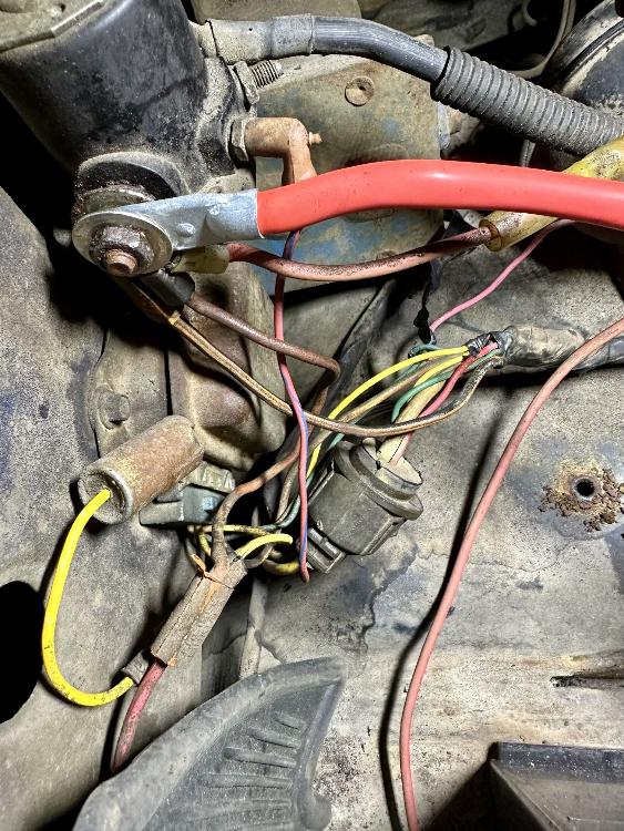
Gary, AKA "Gary fellow": Profile
Dad's: '81 F150 Ranger XLT 4x4: Down for restomod: Full-roller "stroked 351M" w/Trick Flow heads & intake, EEC-V SEFI/E4OD/3.50 gears w/Kevlar clutches
|
Re: Rethinking The 3G Conversion Pages/Process
|
Administrator
|
In reply to this post by dirtymac
I can loop them if that helps, but the EVTM doesn't. They just use the black dot for a splice when things join. The reason we had a problem with those two wires was that they are both yellow.
Let's try to remember this as we go forward and fine tune the schematic. Like Jim's suggestions of eyelets being called out and the megafuse being moved, we have "opportunities".
Gary, AKA "Gary fellow": Profile
Dad's: '81 F150 Ranger XLT 4x4: Down for restomod: Full-roller "stroked 351M" w/Trick Flow heads & intake, EEC-V SEFI/E4OD/3.50 gears w/Kevlar clutches
|
|
Ok that makes sense. I'm still trying to figure out all of the nomenclature in these schematics and I've lost the original image I had found on the forums.
Will
-- 1982 F-250 HD 4x4 400/C6 4.10 Dana61 (Borgeson/Bluetop/Lee, 3G) |
Re: Rethinking The 3G Conversion Pages/Process
|
Administrator
|
Not sure what original image you are looking for, but we should have it.
Anyway, here's what I've done on the engine-side C610 harness. The first shot is just after cutting off the stuff we won't use, but before moving things so you can sorta tell where they went. And the second shot shows things in progress. The small Y/LG wire has an eyelet on it so it can go under the screw that currently grounds the radio capacitor and holds the regulator on the fender. And the R/O wire and the LG/R wire are twisted together with the rest of the LG/R wire laying there to point out where the LG/R wire from the 3G charge harness will go. And the large Y wire, which turns out to be a #12 instead of a #10, is ready for an eyelet. But I don't have one of those so I'll have to order a #10-12 eyelet for a 5/16" stud, which is what the starter relay has. 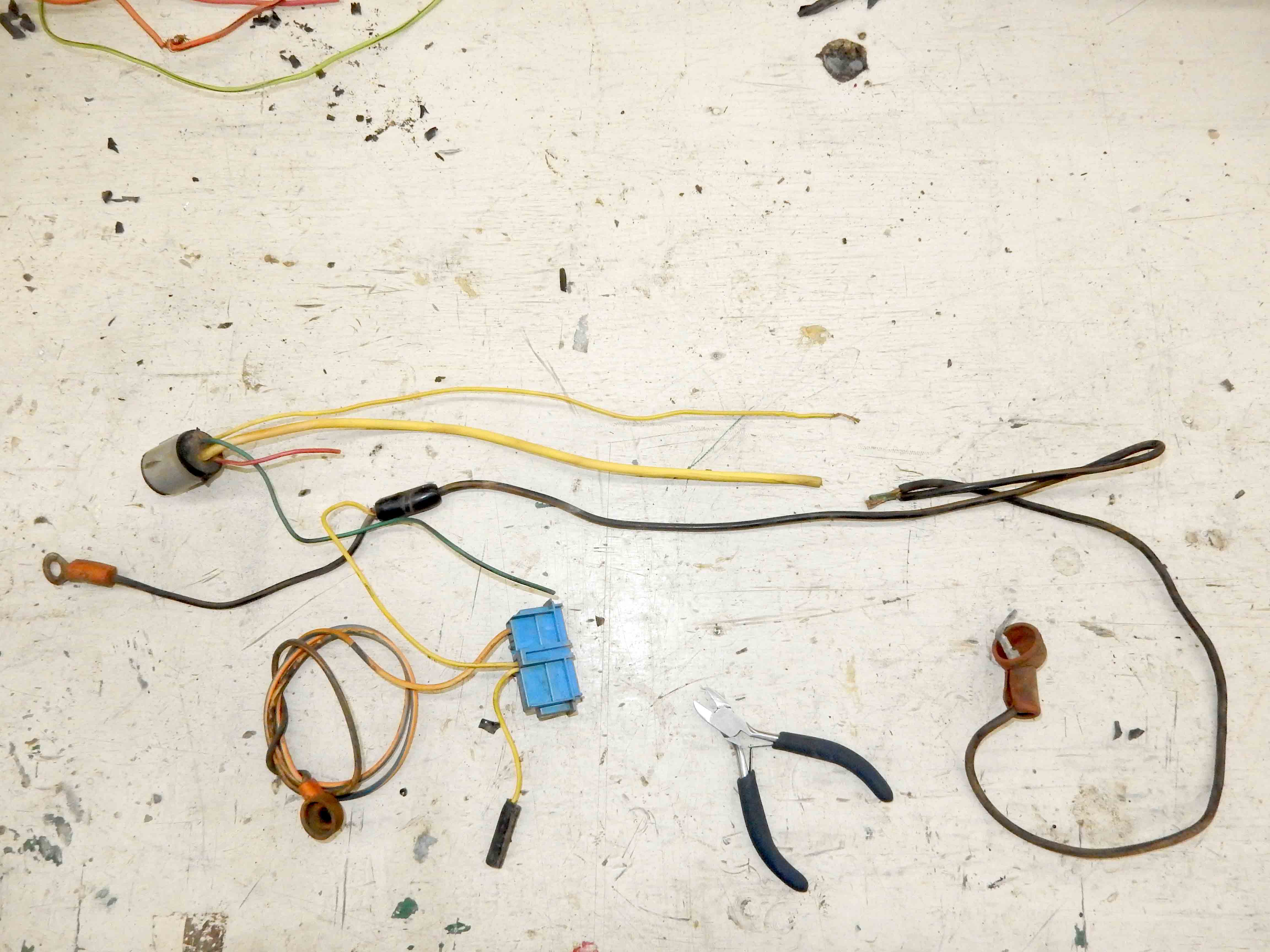 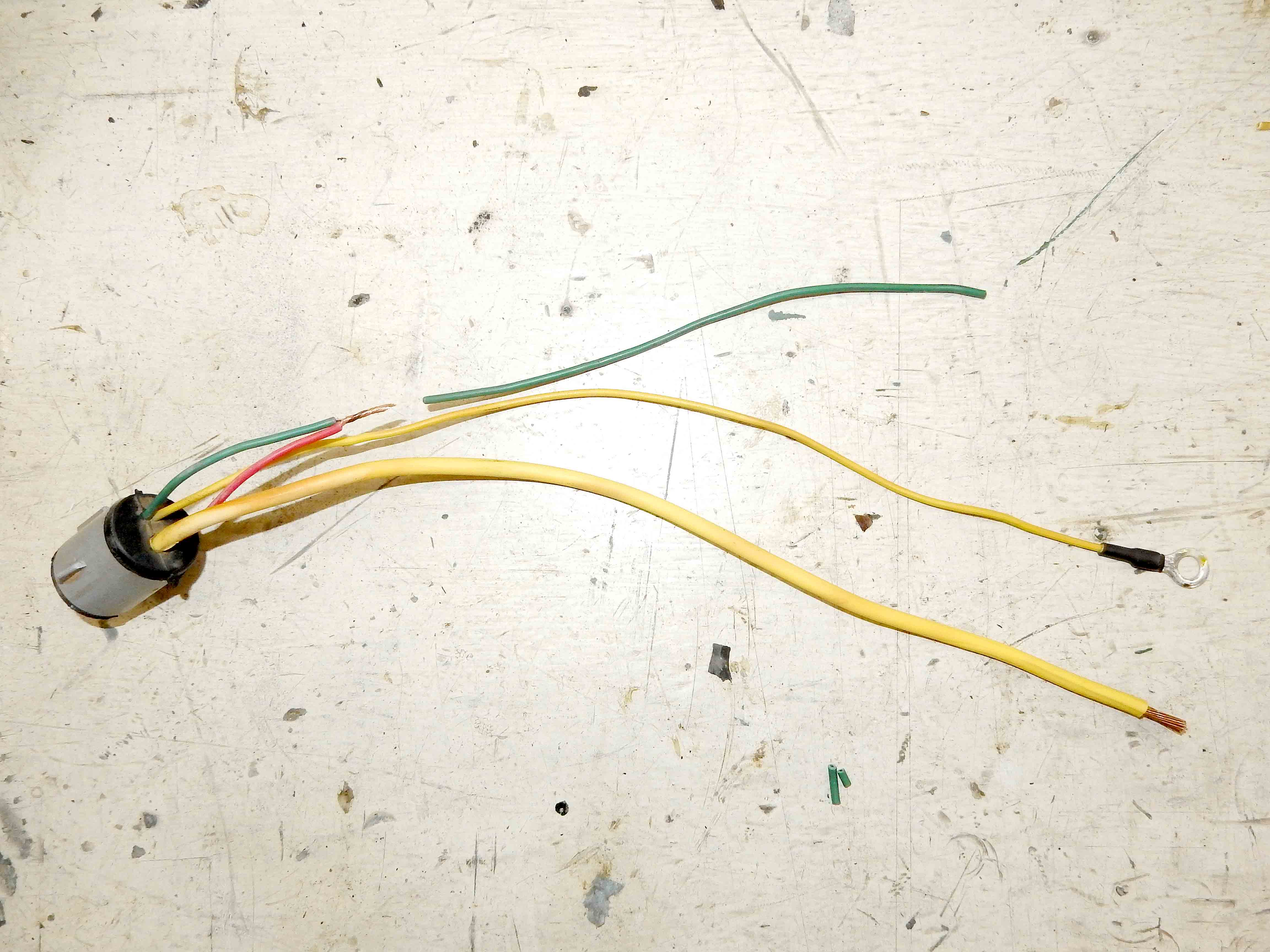
Gary, AKA "Gary fellow": Profile
Dad's: '81 F150 Ranger XLT 4x4: Down for restomod: Full-roller "stroked 351M" w/Trick Flow heads & intake, EEC-V SEFI/E4OD/3.50 gears w/Kevlar clutches
|
Re: Rethinking The 3G Conversion Pages/Process
|
Administrator
|
In reply to this post by Gary Lewis
I used "123" because some people don't seem to "get" XXX and obviously a NEW connector isn't going to be listed in the EVTM tables.
Jim,
Lil'Red is a '87 F250 HD, 4.10's, 1356 4x4, Zf-5, 3G, PMGR, Saginaw PS, desmogged with a Holley 80508 and Performer intake. Too much other stuff to mention. |
Re: Rethinking The 3G Conversion Pages/Process
|
Administrator
|
Ok, Jim, I think I understand. But do we need to number our splices?
Anyway, I'm essentially done. I'll show a couple of pics, but all this needs is a #10-12 eyelet for a 5/16" stud and a "properly sized" fuse. The first pic is of the charge cable I had handy that I'd pulled off another Ford vehicle. The second is of the "almost done" plug & play 3G harness, including a megafuse holder and a link from it to the starter relay. I've assumed that there will be a handy place near the starter relay for the fuse, like where the regulator was. There's plenty of wire to reach that spot, and even a connector to the choke if the truck is using the stator to power it. This should be perfect for a truck with gauges, but we will have to caution people about adding more load in the cab as that #12 yellow wire and/or C610 isn't going to handle much more current. However, that's really no different than with the 1G or 2G alternator as the battery will give them more than 60A of current if they put the load on it. What is different is if they have an aux battery. When the key is turned on the aux battery relay parallels the two batteries and if the aux is dead or low the starting battery will try to bring it up. But that really won't be a lot of current as batteries don't charge batteries all that well. Where the extra current comes from is the alternator, and apparently that #12 wire and C610 is adequate for 60A. But a 3G is a whole different ball game and it would be easy to try to send 100A through there to charge the aux battery. Last, we also need to think about a 3G for a truck w/o gauges, and that turns out to be an easy problem to solve. No C610. In fact, there's no aux battery shown in the EVTM for trucks w/o gauges, so I'm guessing that gauges were required if you ordered an aux battery. 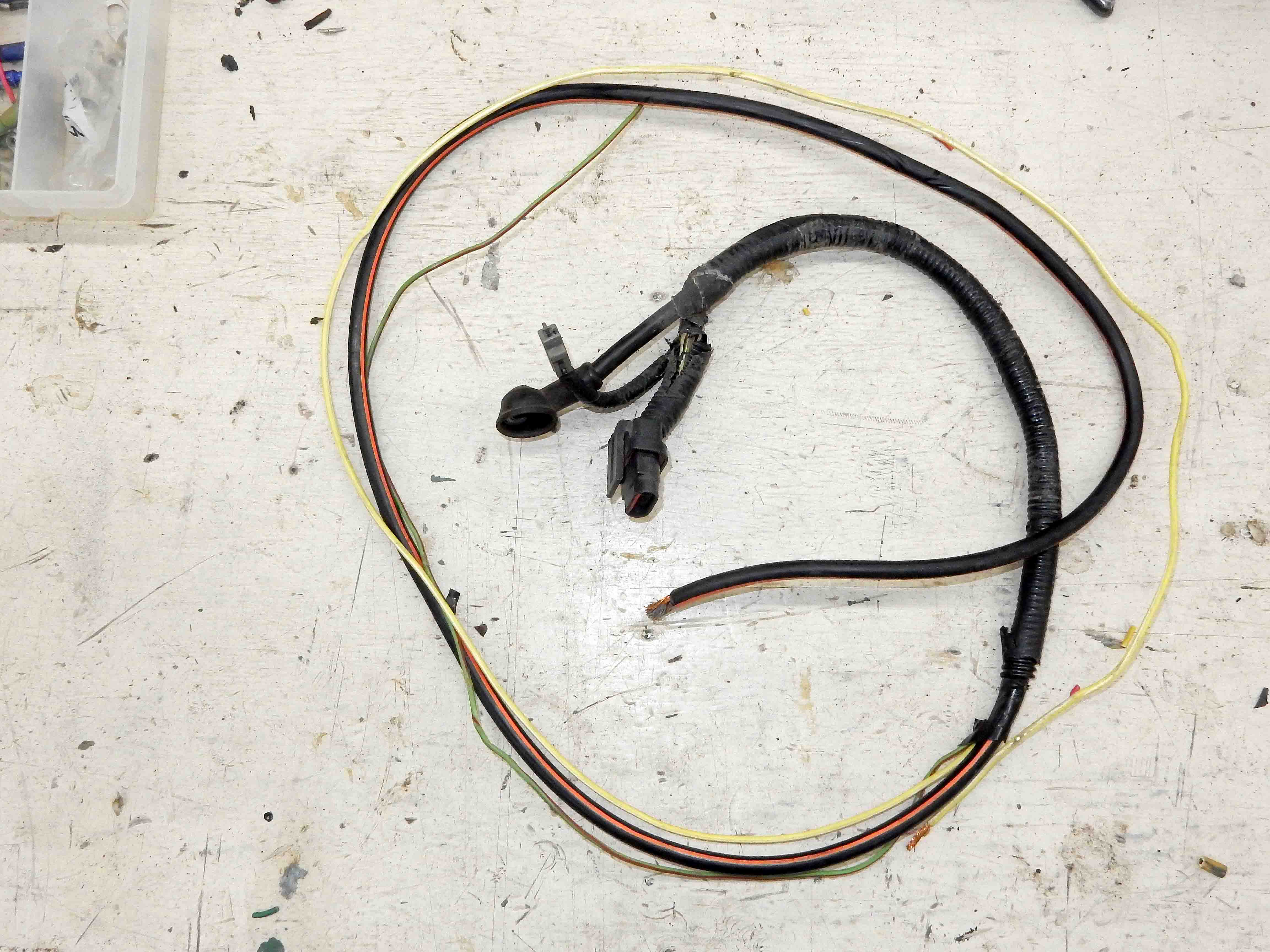 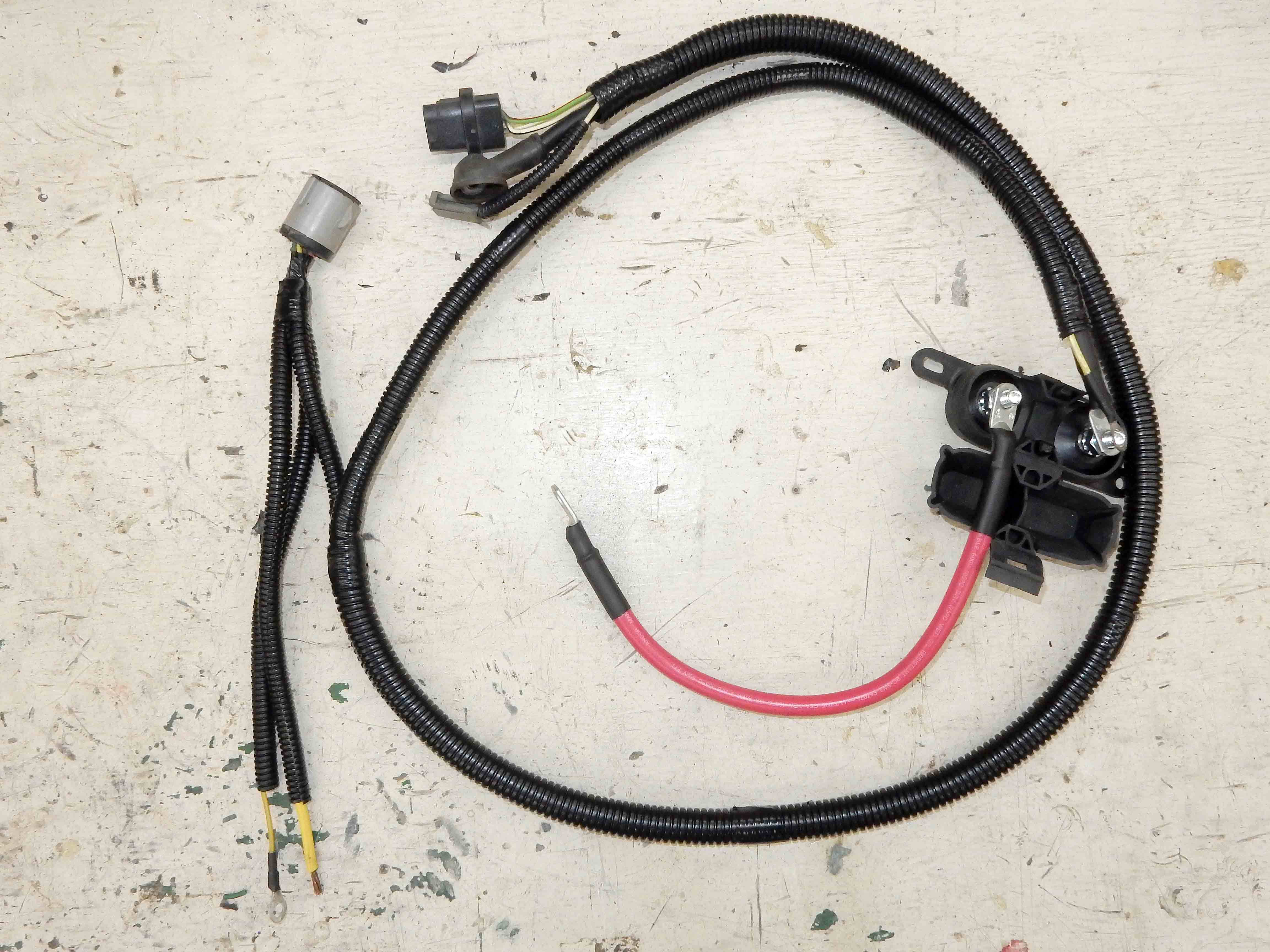
Gary, AKA "Gary fellow": Profile
Dad's: '81 F150 Ranger XLT 4x4: Down for restomod: Full-roller "stroked 351M" w/Trick Flow heads & intake, EEC-V SEFI/E4OD/3.50 gears w/Kevlar clutches
|
|
This looks pretty great to me. I'm comparing it to what I currently have in place and I think this is definitely doable.
I have two questions. First, did you end up soldering anything? The second question is about the white/black stator wire. On the 3G, that wire comes off big plug on the harness and just loops back to a smaller plug which plugs into the alternator as well? For the choke, I would extend the smaller plug up to the choke?
Will
-- 1982 F-250 HD 4x4 400/C6 4.10 Dana61 (Borgeson/Bluetop/Lee, 3G) |
Re: Rethinking The 3G Conversion Pages/Process
|
Administrator
|
Thanks.
I soldered the eyelet onto the Y/LG so it can go to the fender as a ground, and the R/O wire to the LG/R wires, plural, meaning the one coming out of C610 and the one coming from the alternator's big plug. And I used a hydraulic crimper to put the eyelets on the Bk/O wire that is the alternator's output as well as the R wire that is the link from the fuse to the starter relay. And all of those joints were covered with adhesive-lined heat shrink. As for the W/Bk wire, it does come off of the big plug on the harness that connects to the alternator. But it ends in a single-terminal connector that shows as C231 on the schematic. Trucks with a stator-powered choke will have a W/Bk wire coming to the alternator with a matching connector.
Gary, AKA "Gary fellow": Profile
Dad's: '81 F150 Ranger XLT 4x4: Down for restomod: Full-roller "stroked 351M" w/Trick Flow heads & intake, EEC-V SEFI/E4OD/3.50 gears w/Kevlar clutches
|
|
How important are hydraulic crimpers in this? Personally, I do not own a pair. I have a decent set of ratcheting crimpers. I'm also wondering how many people own hydraulic crimpers.
Also, can you tell me about the solder you used? I've heard in the past that soldering stuff under the hood can lead to issues from the heat. I don't have any first hand experience to know if that is an issue but if there are certain solders or techniques to be aware of, I'd like to know.
Will
-- 1982 F-250 HD 4x4 400/C6 4.10 Dana61 (Borgeson/Bluetop/Lee, 3G) |
Re: Rethinking The 3G Conversion Pages/Process
|
Administrator
|
You don't need hydraulic crimpers for wires this size.
Heck you don't really need them to do big 3 & 4/0 cables if you have a bench mounted manual crimping tool. I've got a couple of cheap Iwiss ratcheting hand crimpers. They are fine for down to 8Ga. lugs and terminals
Jim,
Lil'Red is a '87 F250 HD, 4.10's, 1356 4x4, Zf-5, 3G, PMGR, Saginaw PS, desmogged with a Holley 80508 and Performer intake. Too much other stuff to mention. |
| Edit this page |


