3G alternator new or used?
|
Administrator
|
Thanks, Jim. It is fixed.
Gary, AKA "Gary fellow": Profile
Dad's: '81 F150 Ranger XLT 4x4: Down for restomod: Full-roller "stroked 351M" w/Trick Flow heads & intake, EEC-V SEFI/E4OD/3.50 gears w/Kevlar clutches
|
Re: 3G alternator new or used?
|
It appears as though I have hit a snag. I had a plan.... Lol
I was going to get behind the ammeter to test if it's drawing battery power or not. I've got everything removed, except the cluster. I have since learned that there are not wires that plug into the ammeter, it's a circuit board. The idea was to test it and see if it's drawing power, then cut the wire, cap it and all is well. Now, with the circuit board, I'm not sure what to do anymore to find that wire to the ammeter. Is it something I can find in the engine bay somewhere? 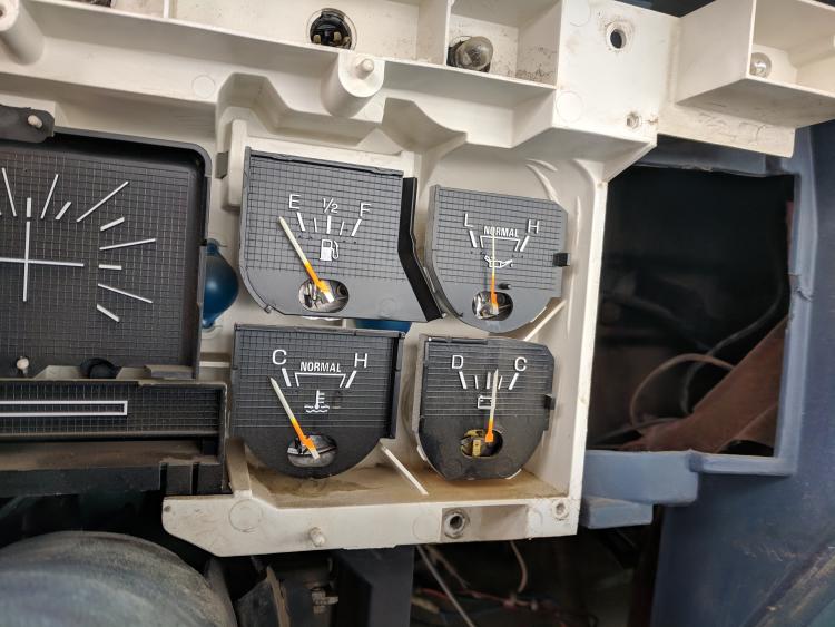
Adam
1986 F-350, Dually 4WD, C/C with the 460/7.5L |
|
Administrator
|
Adam - You are right, you can't really figure it out inside the cab. The shunt we've been talking about shows on Page 17 here (Electrical/1985 EVTM/Charge & Power Distribution (Gas)), right below the ammeter in the illustration.
Note that one end of the shunt hooks to the starter relay/solenoid, and the shunt is a black/orange wire. From the solenoid end of the shunt there is a red/orange wire going to the ammeter, and from the other end of the shunt there's a yellow/light green wire going to the other side of the ammeter. The voltage that is created across the shunt when current flows in it is extremely small. Way, way less than a volt. So small you almost can't measure it with a DVM. And, the ammeter is so sensitive that if you put your DVM on the resistance setting and try to measure the meter you will probably damage it. In reality, when you replace the alternator you need to disconnect the wires going to the ammeter and replace the shunt with a piece of larger wire.
Gary, AKA "Gary fellow": Profile
Dad's: '81 F150 Ranger XLT 4x4: Down for restomod: Full-roller "stroked 351M" w/Trick Flow heads & intake, EEC-V SEFI/E4OD/3.50 gears w/Kevlar clutches
|
|
Banned User
|
In reply to this post by ArdWrknTrk
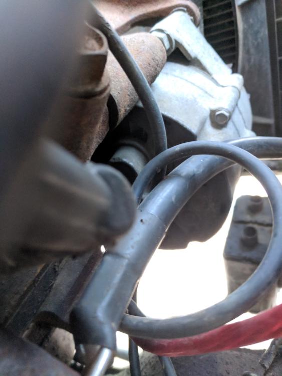
It's certainly not. Your pic clearly shows an external fan on the alt (which is characteristic of the 1G & 2G). The ~5x5" steel box on the fender would be the external voltage regulator, as this pic shows:  That's pretty scary, and likely a BIG part of your charging problems. The alt body should be TIGHT between the bracket & bolt head (with sliding sleeve, which your bracket still has); and the bracket should be TIGHT to the head or block; and ALL those mating surfaces should be clean & shiny metal (with electrical grease applied - NOT dielectric, or chassis, or thermal, or battery snot, or anti-sieze, or...). Try to get a well-lit focused pic showing all the wire connections on the back of the alt. My impression is that your pic shows a 1G, but there's not actually enough visible to be sure. Your alt is only marginally-tight to the bracket due to the nut & washer behind it (visible in the 2nd pic). But that same nut & washer are also PREVENTING the bracket from being truly tight against the head at that location. It should be a simple LONG bolt, and the alt body should take up all the gap between the back of the bracket & the sliding sleeve in the front of the bracket. A spacer is OK, but not ideal. Most circuits need protection, and the original protection for the charging circuit was a fusible link wire (a normal wire inside special insulation sized to burn out under specific conditions). But Ford changed the circuit design on later 3Gs & all subsequent alt.s to a MEGA fuse, which is easier for most people to understand & replace. So it's a good idea to swap to that when you swap to a 3G, and it's cheap & easy if you get a used 3G since you can get that harness section with fuses at the same JY. This one also has a fuse on the small Y wire:  D(rain) & C(harge). That it doesn't work proves nothing - they didn't really work new, which is another reason to get rid of that circuit, and switch to a true voltmeter (like all modern vehicles).
The shunt isn't a coil; it's not all in the dash; it's not really resistor wire; and it would never glow. It's a normal heavy Copper wire in the harness sections from the starter relay area to the ignition switch area. It might be wrapped or folded inside the harness to get the designed length, but it's not really "coiled". It has resistance only because it's old Copper - they didn't have the infrastructure back then to process Cu as purely as we have now. But it was never designed to have a specific resistance; they just used its natural resistance for the gauge. If you try to run a HO alt through it, the connectors would burn out long before the wire got hot enough to glow, or even melt its insulation. But those connections COULD still start a fire. That's actually all he needs to find it right there on the back of the cluster, inside the cab. Any modern DMM (even a $10 one) is vastly more-sensitive & -accurate than that old gauge. And the gauge isn't delicate at all - any DMM has ~10,000x more resistance than that old gauge, so the meter won't hurt the gauge. The shunt is large enough for what it will be doing after the alternator output is run directly to the starter relay (battery side), so it's not worth the effort or risk to pull a wire out of the harness. Just disconnect & tag the gauge wires, in case you find some other use for them later (like LEDs...). |
|
Administrator
|
I stand corrected Steve.
Should have said bundle instead of coil. While I have to think 'resistance' is probably my phone's autocorrect for *resistive. The "ammeter" is a good example of the time honored voltage drop test, often suggested for finding something like an internally corroded ground or starter cable. Anyway, good observations and succinct answers. Hopefully this clears things up and helps Adam get his truck going
Jim,
Lil'Red is a '87 F250 HD, 4.10's, 1356 4x4, Zf-5, 3G, PMGR, Saginaw PS, desmogged with a Holley 80508 and Performer intake. Too much other stuff to mention. |
|
Administrator
|
In reply to this post by Steve83
Steve - I pulled an ammeter off the shelf and did some testing.
Full scale in the "C" direction takes only .170 volts. But, at that point it there is 1.0 amp running through the ammeter.Full scale in the "D" direction takes only .150 volts. And at that point there's .88 amp running through the ammeter.So, even a cheap DVM can measure the voltage when the alternator is kicking out something like its full capability. But, it takes about .02v to start seeing any movement on the ammeter, so that could be missed. And, I agree with you on the shunt being adequate to handle the normal load in the cab and, therefore, doesn't need to be replaced if the alternator's output is moved to the battery side of the solenoid. And especially if lights are replaced with LED's. But, I wouldn't want to start adding a lot of current hogs, like large audio amps, to the shunt's load. Anything big like that should have its own power source from the battery rather than come through the fuse box. But, for grins I used the E=IR equation to calculate the resistance of the shunt. Assuming that it was designed to handle the 70 amp alternators that could come in these trucks, the shunt would have to be .002285 ohms to create .16 volts across it, which is the average of the .15 and .17 that I measured. As it turns out, #14 wire has 2.525 ohms per 1000', or .0025 ohms per foot. So, that would be about right for the shunt. But, the tables say you should not run more than 32 amps through #14 wire, probably for fear that the insulation will melt or the wire will become brittle with the heat. Perhaps shunts are made of special wire and/or have special insulation like fuse links do? Wondering about the heat I used the equation that Watts = IxIxR and found that the heat produced in the shunt at 70 amps would be 11.2 watts. It isn't likely that the wire would get very hot with that much heat. But, I don't have an easy way to test that theory so don't know for sure. Last, the use of the wires to the ammeter is to run a voltmeter. That's my plan anyway. Ground one and put switched battery voltage to the other. I have already had Rocketman convert the ammeter to a voltmeter. 
Gary, AKA "Gary fellow": Profile
Dad's: '81 F150 Ranger XLT 4x4: Down for restomod: Full-roller "stroked 351M" w/Trick Flow heads & intake, EEC-V SEFI/E4OD/3.50 gears w/Kevlar clutches
|
|
Today my bone stock truck fell victim to the 2G fire. I had to douse the flames with a water spray bottle (on an electrical fire!) and in doing so the 16GA fusable link solenoid wire on the RH fender blew out.
Here’s a photo of the wire for your entertainment. 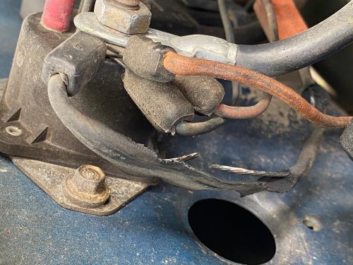 I read on this site the following on alternator fires: “There has been a recent investigation of alternators manufactured by Ford. This article provides facts and information from the Ford investigation. In one instance, the driver smelled smoke and discovered a fire underneath the hood of his Ford Aerostar. After the Fire Company extinguished the fire, investigators determined that the wiring at the plug connector melted and caused high resistance overload. According to the National Highway Traffic Safety Administration (NHTSA) there are 75 fires allegedly caused by the Ford Alternator. Ford uses a plug connector and not the conventional attachment. Investigators think that this plug connector develops high resistance over time and becomes even more dangerous when it is removed and reconnected. Currently Ford and the NHTSA are conducting further investigations into Ford alternators.” I also read the comments about swapping it out to avoid potential fires (never expecting it on my truck), and so here’s my stupid question of the day: Would Ford (dealership) do anything about this, or is it on me to fix?
1984 Bronco 351 Holley Sniper EFI, 3 Speed Ford Auto.
1986 Bronco 302 EFI, AOD, Eddie Bauer, with 3G alternator. |
|
Administrator
|
The only stupid question is the one you didn't ask, and you asked this one so it isn't stupid. However, I think the answer would be accompanied by
 . But, if it was me I'd ask. . But, if it was me I'd ask.
Just FYI, we have a TSB on the 2G problem on the site here: http://www.garysgaragemahal.com/96-21-04-2g-alternator-repair.html Anyway, sorry about your truck. Glad you got the fire out quickly.
Gary, AKA "Gary fellow": Profile
Dad's: '81 F150 Ranger XLT 4x4: Down for restomod: Full-roller "stroked 351M" w/Trick Flow heads & intake, EEC-V SEFI/E4OD/3.50 gears w/Kevlar clutches
|
|
Administrator
|
In reply to this post by Vic Roma
Really glad you didn't lose the truck Vic! 🙏
No, they're not going to do anything about a popped fuse link. But what you can do is upgrade to the much safer 3G alternator, and use a HMEG with a fuse instead of relying on an undersized wire to protect your truck.
Jim,
Lil'Red is a '87 F250 HD, 4.10's, 1356 4x4, Zf-5, 3G, PMGR, Saginaw PS, desmogged with a Holley 80508 and Performer intake. Too much other stuff to mention. |
|
Thanks Gary, Jim. I too am SO relieved it didn’t self-immolate. Glad I made you laugh.
I know full well it was a stupid question, but I was hoping someone might have said yes you can do something like a product recall... The motivation was I had an airbag product recall on a 2004 car where they swapped it out. It was wishful thinking. BTW I was also referring to claiming for the alternator that was billowing plumes of smoke like it was sending distress signals to a neighboring tribe, not the blown wire. Anyhow, it’s time for the upgrade for sure, no choice really. Instead of hunting for a used Taurus alternator and harness etc., is it worth buying a *new* 130A Motorcraft alternator, or some other decent brand (need to research) with higher output? I vaguely remember reading somewhere in the documentation and/or comments that any more than 130 and I could fry my wires (again!). Is this true? I was under the impression an alternator should only pump out what the systems demands, and no more.
1984 Bronco 351 Holley Sniper EFI, 3 Speed Ford Auto.
1986 Bronco 302 EFI, AOD, Eddie Bauer, with 3G alternator. |
|
Administrator
|
This post was updated on .
You have a choice of 95A or 130A 3G.
I bought an inexpensive one from JB electrical and just commented the other day that it's been trouble free since I installed a LRC (white) regulator, and it doesn't chirp on startup any more. An alternator SHOULD only put out what is called for. That's the regulators function. In the 2G the charge plug gets corroded, or that twinned fuse link fails and the regulator goes full field until the alternator kills itself. (the cause of the alternator meltdown) It's either charging into a void, or the plug melts and it starts charging into a dead short on its own case. Either way the windings and diode board can't last for long like that. When we do a 3G swap we take the yellow "sense" wire and loop it right over to the output stud. There should be no way to have a meltdown unless that 3" of wire gets cut.
Jim,
Lil'Red is a '87 F250 HD, 4.10's, 1356 4x4, Zf-5, 3G, PMGR, Saginaw PS, desmogged with a Holley 80508 and Performer intake. Too much other stuff to mention. |
|
Administrator
|
In reply to this post by Vic Roma
I didn't address this. --You can fry the shunt wire if you have an ammeter AND have a big load somewhere on the cab wiring-- The 3G output should always be fused. You can get MegaFuses of many sizes. By connecting to the other side of the shunt the ammeter no longer works but there is no danger of wires melting. The recommended solution is to have the ammeter converted to a voltmeter, and have it wired to key on power. It looks stock and doesn't limit any current you need flowing.
Jim,
Lil'Red is a '87 F250 HD, 4.10's, 1356 4x4, Zf-5, 3G, PMGR, Saginaw PS, desmogged with a Holley 80508 and Performer intake. Too much other stuff to mention. |
|
Thanks, Jim.
In preparation for an eventual 3G upgrade, last year I bought a converted ammeter from Bob. Out of curiosity, is it possible to go higher than 130A?
1984 Bronco 351 Holley Sniper EFI, 3 Speed Ford Auto.
1986 Bronco 302 EFI, AOD, Eddie Bauer, with 3G alternator. |
|
Administrator
|
There are updated 3G alternators with thicker copper traces on the diode board and bigger heatsink.
Bill Voss has a 160A in Darth, his '86 dually. The limit really is how much torque a belt can transmit. Single V belt will start slipping before 100A and the polygroove belt on later trucks probably won't go much more than 140-150. Ambulance equipped E3/450's had a 200A Mitsubishi alternator with a much wider ribbed belt.
Jim,
Lil'Red is a '87 F250 HD, 4.10's, 1356 4x4, Zf-5, 3G, PMGR, Saginaw PS, desmogged with a Holley 80508 and Performer intake. Too much other stuff to mention. |
|
Administrator
|
Vic - Jim has laid it all out, but most of that is also on our page here: Documentation/Electrical/3G Conversion.
As for going with more than 160 amps, in theory I did that for Dad's by replacing the diodes with one capable of 160 amps. And I replaced the standard regulator with one that brings the current on slowly (LRC) as it will be run by twin v-belts. But that alternator hasn't been run yet, so I can't say it works. However, if I had to find an 3G alternator today, I'd do as Jim did and by one from DB Electrical. The page above says "For instance, DB Electrical currently (2/8/2019) sells the F4PZ 10346-B from the list above for from $78 for a 130 amp unit up to $278 for a 220 amp unit - with a 1-year warranty." How badly do you need the extra current? 
Gary, AKA "Gary fellow": Profile
Dad's: '81 F150 Ranger XLT 4x4: Down for restomod: Full-roller "stroked 351M" w/Trick Flow heads & intake, EEC-V SEFI/E4OD/3.50 gears w/Kevlar clutches
|
|
Administrator
|
ISWYDT  Your next tutorial needs to be: Converting your alternator to 520 chain drive for MOAR Amps!
Jim,
Lil'Red is a '87 F250 HD, 4.10's, 1356 4x4, Zf-5, 3G, PMGR, Saginaw PS, desmogged with a Holley 80508 and Performer intake. Too much other stuff to mention. |
|
Administrator
|
That was just serendipity. A slip of the fingers.
 But yes, it would take a serious drive system to power an alternator while it put out 220 amps. Probably a gilmer belt?
Gary, AKA "Gary fellow": Profile
Dad's: '81 F150 Ranger XLT 4x4: Down for restomod: Full-roller "stroked 351M" w/Trick Flow heads & intake, EEC-V SEFI/E4OD/3.50 gears w/Kevlar clutches
|
|
In reply to this post by Gary Lewis
Yep that is the alternator I keep looking at for my conversion for my truck but I still am holding out hope all my reading and research will net me a 95A wide ear 3G alternator but I think id have a better chance photographing bigfoot riding a unicorn at this stage as I just dont believe it exist anymore if it even existed at one time.
Just sucks for me cause my plan was for the 95A and gauge wise I am hoping to just toss my whole OE cluster for one of the RTX gauges from Dakota Digital for our trucks when they release it. There are cheaper 3G`s though on rock auto brand new than from DB Electrical but you have to know what you are looking for year/make/model wise.
"Old Blue" - '56 Fairlane Town Sedan - 292-4V, Ford-O-Matic transmission, 3.22:1
'63 Belair 2dr sdn - 283-4V, Powerglide transmission, 4.56:1 '78 Cougar XR7 - 351-2V, FMX transmission, 2.75:1 9inch "Bruno" - '82 F150 Flareside - 302-2V, C6 transmission, 2.75:1 9inch, 31x10.50-15 BFG KO2 |
|
In reply to this post by Gary Lewis
"How badly do you need the extra current?"
Now that I know better, not badly at all. I finally have a 3G alternator ready for the install. I am unsure what to do with the harness from splice S204 to C610. As others have found out, there are many online videos, articles and forum posts of how to upgrade, but many pertain to Fox-body Mustangs and later model trucks, and few that explain (clearly) how to modify the harness such as I have. Hopefully this post is a comprehensive tutorial for the uninitiated. Searching for 3G related posts and reading the content, Gary, I saw your statement "...the shunt needs to be removed if you go to a high-output alternator as they have been known to melt when not removed." In order to clean up the wiring now that I have the chance, which wires can I remove to make the entire upgrade more efficient/clean, which do I connect to the new harness, and/or the battery side of the starter relay? 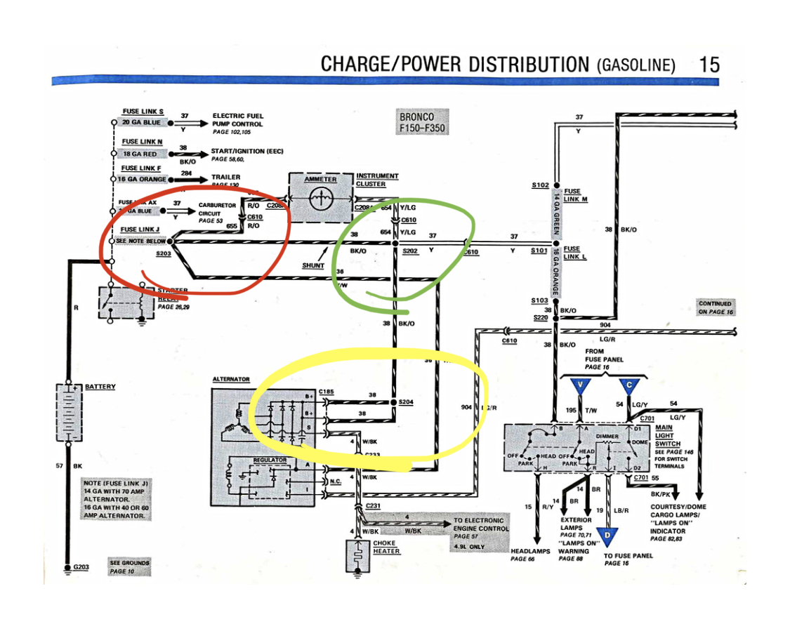 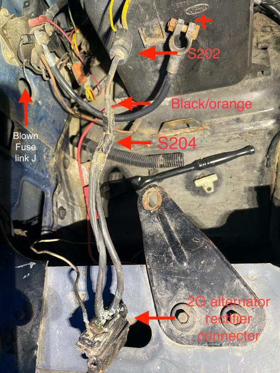 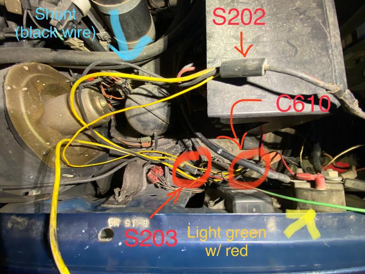 Using the above as reference: - Do I cut the splice S204 (see EVTM, circled in yellow) and attach it to the alternator's output stud, as well as run the (Painless 3G harness) heavy gauge red wire from the same output post through a mega fuse to the battery? - If I remove the black shunt wire, do I cut it out entirely, or merely disconnect from splice S202 (but keep it connected at splice S203), and cap it off for later use? Steve83 wrote, "The shunt is large enough for what it will be doing after the alternator output is run directly to the starter relay (battery side), so it's not worth the effort or risk to pull a wire out of the harness. Just disconnect & tag the gauge wires, in case you find some other use for them later (like LEDs...)." - Do I still need to replace the 16GA Fusible Link (that exploded), as it branches off at S203 to a red wire that leads to one side of the ammeter, and the other to the yellow wire from the 2G ASI connector (in the bottom picture, it's hanging over the fender)? I'm guessing yes but if the new 3G ASI yellow wire can connect to the output post, then where does the 2G yellow wire go? If the shunt is gone, then S203 loses the yellow and black, so to where do the red and fuse link J connect? Just want to be sure before I cut and regret.
1984 Bronco 351 Holley Sniper EFI, 3 Speed Ford Auto.
1986 Bronco 302 EFI, AOD, Eddie Bauer, with 3G alternator. |
| Edit this page |


