Introducing Myself
|
Hi - well so, I scratched my head a lot and finally tabled to effort last year, but back at it again with new vigor. After looking at this diagram again fresh I think I finally have it figured out in my head. I don’t have the ammeter converted yet so thinking to just reconnect everything except the yellow wire for now and leave It for when I get the ammeter converted to a voltmeter. Is there any reason not to do that?
Thanks, Brian |
Re: Introducing Myself/Need some more advice
|
Administrator
|
If by "the yellow wire" you mean the yellow white wire, then the alternator won't work if you don't hook that wire up. Or, maybe I should say it'll work w/o regulation and the output voltage will go very high. Don't do that.
But if what you are worried about is the ammeter, then you could do the 3G conversion and leave the ammeter. It is a bit risky as the shunt may melt if the alternator is required to recharge a dead or very low battery. But if you are careful and charge the battery up before starting the truck the first time you should be ok.
Gary, AKA "Gary fellow": Profile
Dad's: '81 F150 Ranger XLT 4x4: Down for restomod: Full-roller "stroked 351M" w/Trick Flow heads & intake, EEC-V SEFI/E4OD/3.50 gears w/Kevlar clutches
|
|
That make sense about the yellow/white wire coming from the regulator. But there is a 10 gauge all yellow wire that is spliced onto the charge wire and into a connector together with the ignition wire coming from the reg. I was figuring that was the shunt and only used to detect charge condition and had nothing to do with regulation
|
Re: Introducing Myself/Need some more advice
|
Administrator
|
The wiring is shown below, which is out of the 1985 EVTM here: http://www.garysgaragemahal.com/charge--power-distribution-gas.html on Page 17. And if the wire circled in red is the one you mean it won't work leaving it off. If you turn to Page 18 in the EVTM, shown further below, you'll see where that yellow wire goes - to the ignition switch. It feeds a lot of things, including the ignition.
The shunt is the black/orange wire, marked Shunt in the first diagram, and it is what isn't up to handling the full output of the 3G alternator. It is probably rated at a max of 70 amps as the largest alternator available on these trucks was a 70a unit. So you might get by leaving the shunt in if you never run the battery down very low, which would require the alternator to go to max output. Or you can wire around the shunt. Run a #10 wire between the two connections circled in maroon and that will bypass the shunt as well as the ammeter. Good to go. 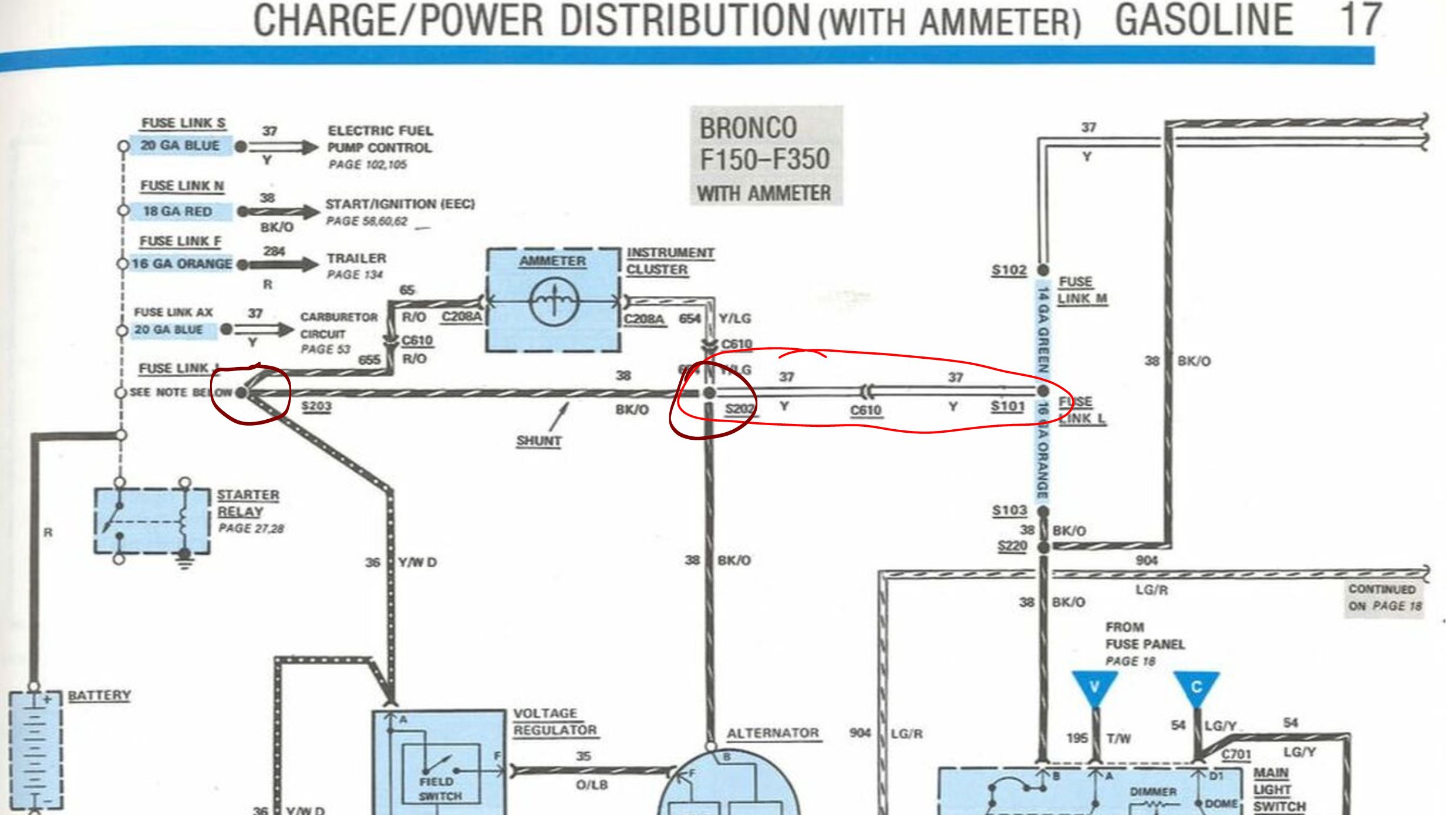 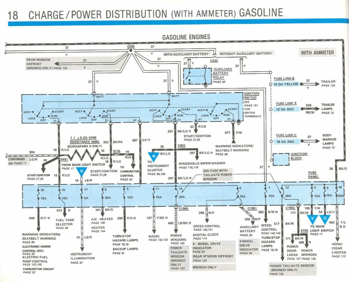
Gary, AKA "Gary fellow": Profile
Dad's: '81 F150 Ranger XLT 4x4: Down for restomod: Full-roller "stroked 351M" w/Trick Flow heads & intake, EEC-V SEFI/E4OD/3.50 gears w/Kevlar clutches
|
|
Gary - I have noted 2 different configurations for how to wire the A yellow wire coming from the regulator. In your schematic, it shows it going straight to the battery side terminal of the solenoid, bypassing the fuse. In the schematic that came with the alternator/harness, it shows that wire going to the B terminal of the alternator and thru the fuse. Is there is case for bypassing the fuse that would justify undoing how the harness came from the supplier and splicing it connect it at the solenoid as depicted in the physical depiction your provided previously. Also, I am still not certain what to do about the ammeter. In your last note, you said to run a 10 wire splice between the 2 maroon circles on the schematic in order to bypass the shunt, , but that looks like the same thing as the shunt to me?
Thanks, Brian |
|
This post was updated on .
3gComparison.JPGForgot to attach pic of the competing diagrams
|
Re: Introducing Myself/Need some more advice
|
Administrator
|
In reply to this post by Schwabber
Brian - The part you've missed is that the diagrams above are for the original alternator, not the 3G. I only showed them to discuss the shunt. And while I'm on that subject, yes you do need to run a 10 gauge wire between those two maroon circles. The 10 gauge wire is much larger than the shunt and will have essentially no voltage drop across it so the ammeter won't burn out, nor will the shunt.
As for the diagram, you are supposed to use the one on the 3G page, shown below for convenience. It is essentially the same as the top diagram in your link. But those are for a truck with a warning light. Unfortunately I don't have one for a truck with an ammeter on the site. And I can't see enough of the lower diagram in your link to know where it is getting its power going to the "I" terminal on the alternator. So, can you get a better pic of that diagram and include the part in the lower right corner? 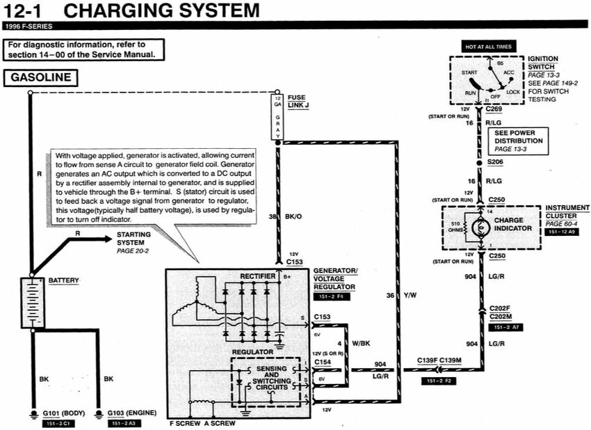
Gary, AKA "Gary fellow": Profile
Dad's: '81 F150 Ranger XLT 4x4: Down for restomod: Full-roller "stroked 351M" w/Trick Flow heads & intake, EEC-V SEFI/E4OD/3.50 gears w/Kevlar clutches
|
|
Gary, it occurs to me that another possible source of confusion here is that I have not fully described how I am going about my solution. I am not using the existing original harness at all - the one on the truck was fried and I could not find a donor vehicle. So, I am using a 4 ga charging wire going direct from the Alt B terminal to the 175 a fuse to the battery side of the solenoid. From my understanding of prior discussion, it seems to me that this should prevent frying the shunt, but at the same time the ammeter will be always showing a draw condition even if/when the alternator is charging. If this is correct, then I think I am ok with that. I do plan to convert the ammeter to a voltmeter as discussed elsewhere, but it sounds to me as though that change is not a precondition to getting the alternator installed and the truck running again.
The other question unresolved with this approach, is what to do with the yellow charge wire discussed previously. I gather that I will need to connect a 12 ga wire to the battery side of the solenoid on top of the 4 ga wire coming from the alt, and splice that into the existing 12 ga yellow wire that goes into the connector and off to the dash with the ignition wire. I've attached the full diagram from the provider of the harness, and a photo of the connector described above 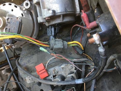 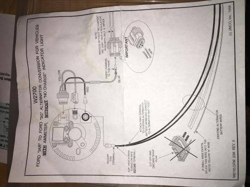 Thanks for sticking with me on this. I imagine this must me a real pain for you too. ;) |
Re: Introducing Myself/Need some more advice
|
Administrator
|
This post was updated on .
In reply to this post by Schwabber
Maybe I can help? The 'A' wire is 'alternator' and senses system voltage at the alternator. It could be at the actual output post, or the alternator side of the 175A fuse. If for some reason that fuse were to blow, break or corrode the alternator would go 'full field' and meltdown in just a few minutes. This is why it should be attached before the fuse. The existing B/O wire between the two circles is deliberately undersized for the 60?A alternator you have. This forces some current to flow through the a meter, and this is what the meter reads. The 3G can put out twice as much amperage, and the existing shunt is far too small to handle that. If you had a high current draw it would try to find the path of least resistance, and as the shunt heated up more current would try and find its way through the meter, probably melting it or (in an extreme case) causing a fire. So you replace the shunt with a 10Ga. wire that can handle all the cab loads.
Jim,
Lil'Red is a '87 F250 HD, 4.10's, 1356 4x4, Zf-5, 3G, PMGR, Saginaw PS, desmogged with a Holley 80508 and Performer intake. Too much other stuff to mention. |
Re: Introducing Myself/Need some more advice
|
Administrator
|
Thanks, Jim!

Gary, AKA "Gary fellow": Profile
Dad's: '81 F150 Ranger XLT 4x4: Down for restomod: Full-roller "stroked 351M" w/Trick Flow heads & intake, EEC-V SEFI/E4OD/3.50 gears w/Kevlar clutches
|
Re: Introducing Myself/Need some more advice
|
Administrator
|
This post was updated on .
I don't know if it will help.
I'm just trying to be consise and complete. From the diagrams posted I'm assuming Brian bought some kind of harness from PA Performance.
Jim,
Lil'Red is a '87 F250 HD, 4.10's, 1356 4x4, Zf-5, 3G, PMGR, Saginaw PS, desmogged with a Holley 80508 and Performer intake. Too much other stuff to mention. |
|
In reply to this post by ArdWrknTrk
Thanks, Jim - that helps a lot.
I still do have some uncertainty around the physical location of those nodes that are circled in maroon on the schematic. I suppose this is my relative inexperience with automotive schematics here, but I think it could also be somewhat related to work done on the vehicle prior to my getting it. Is what is depicted as the first node coming from the B terminal the splice that includes that small yellow(perhaps 16 gauge), the orange/black wire(the shunt?), and the 12 gauge yellow wire?("Node1" photo) And is the other node the splice with the approx 16 gauge red and yellow wire that go to and that goes over to the connector, with the black/orange fuse link that is seen fried in the background of the "Node2" pic. If that is correct understanding, then I am not sure how to work this into my new set up. I am running a 4 gauge wire off the B terminal of the alt to the mega fuse. I cant see how I would want to splice into this charge wire. So, are these the nodes being referenced, or am I barking up the wrong tree? Also, I had been thinking was that with this new approach I had been contemplating, I would need to bring a 10 or 12 gauge yellow wire from the battery post of the solenoid to a splice point on the existing 10/12 gauge wire seen in the "Node2" pic so that what all that wire is powering under the dash continues getting it's power source. 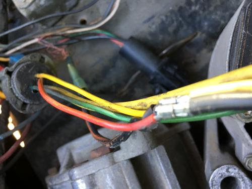 Node 2 Node 2
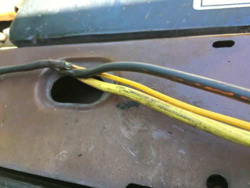 Node 1 Node 1
|
Re: Introducing Myself/Need some more advice
|
Administrator
|
This post was updated on .
One of the advantages (and downfalls) of the Electrical and Vacuum Testing Manual is that only the circuit in question is shown.
So you may see a (C) connection, or a (S) splice that appears to have fewer wires than in real life. In the diagrams they are always numbered. e.g. C257, but you may only see 3 wires represented. On another page you may see C257 mentioned again with another 4 (but different) wires! **it's all in the same plug** This is so one can focus on the circuit at issue, but can seem confusing to the uninitiated. It does appear that someone used a butt crimp (splice) to replace the fuselink. (which burned up again) So who really knows what else has been misrepaired. (a new word!) I see the instruction page you posted.. Are you trying to use some kit, or are you starting from scratch? Give me a moment to open all these posts in tabs, so I don't have to scroll across posts to see the diagrams. Working from a mobile device can be challenging.
Jim,
Lil'Red is a '87 F250 HD, 4.10's, 1356 4x4, Zf-5, 3G, PMGR, Saginaw PS, desmogged with a Holley 80508 and Performer intake. Too much other stuff to mention. |
Re: Introducing Myself/Need some more advice
|
Administrator
|
This post was updated on .
In reply to this post by Schwabber
So, those are the S202 and S203 splices that Gary circled.
The Black/Orange (shunt) wire between them must be replaced with a wire of 10 AWG. (6.0 mm section) The small Red/Orange and Yellow/Green wires are the ones that connect the ammeter. The Black/Orange wire coming from your alternator will be replaced by the 4Ga. cable going to the Megafuse. Now I ask about the kit. Is this the PA Performance kit with the false 'regulator' box? Is it their usual 3G conversion kit? It helps to know what you have to work with, so I can give correct advice. Just show me what you have and I can tell you how to make it work.
Jim,
Lil'Red is a '87 F250 HD, 4.10's, 1356 4x4, Zf-5, 3G, PMGR, Saginaw PS, desmogged with a Holley 80508 and Performer intake. Too much other stuff to mention. |
|
Jim -
I picked up the harness together with the alternator from a place called Quality Power. The harness was presented as a "2g to 3g" upgrade harness. The regulator is standard as seen below Thanks much for the assist. 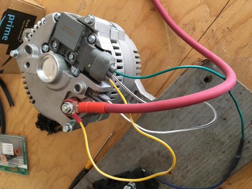
|
Re: Introducing Myself/Need some more advice
|
Administrator
|
Gosh Brian, I'm sorry I dropped the ball.
Gary edited out a bunch of banter we had hijacked your thread with and I followed it into Big Blues thread. Never noticed you replied here.  Ok. So I see where the instructions show cutting off the plug and it says "if this wire exists, splice it into the yellow (B) wire." But since you're not using the pair of B/O wires and their fuselink anyway you should try to unwrap this yellow(?) wire back up to the main harness. Instead of 'splice' you could put a ring terminal and add it to the fuse holder or hot side of the starter relay. Unfortunately Gary doesn't seem to have an EVTM page showing the 2G in a bullnose with an ammeter. I'll have to find that diagram, but I think you don't really need it since the regulator plug you have now is looped to the output stud. Let me double check. Because I don't want to miss something WRT your specific year and model.
Jim,
Lil'Red is a '87 F250 HD, 4.10's, 1356 4x4, Zf-5, 3G, PMGR, Saginaw PS, desmogged with a Holley 80508 and Performer intake. Too much other stuff to mention. |
Re: Introducing Myself/Need some more advice
|
Administrator
|
This post was updated on .
An off topic question:
I see you say you're from Northern California, Bay Area. As an east* coaster I've always thought of San Francisco as central California, and that you had to be above Marin and Sonoma before it was 'northern'? Maybe a line straight west from Tahoe, in the crook? I think of Mendocino or Ft. Bragg as northern, and below Santa Barbara as southern, but I guess I'm too literal? What's the consensus, from a Californian perspective?
Jim,
Lil'Red is a '87 F250 HD, 4.10's, 1356 4x4, Zf-5, 3G, PMGR, Saginaw PS, desmogged with a Holley 80508 and Performer intake. Too much other stuff to mention. |
Re: Introducing Myself/Need some more advice
|
Administrator
|
In reply to this post by ArdWrknTrk
Jim - The Electrical/1986 EVTM/Charge & Power Distribution Gasoline Engines has this one: 
Gary, AKA "Gary fellow": Profile
Dad's: '81 F150 Ranger XLT 4x4: Down for restomod: Full-roller "stroked 351M" w/Trick Flow heads & intake, EEC-V SEFI/E4OD/3.50 gears w/Kevlar clutches
|
Re: Introducing Myself/Need some more advice
|
Administrator
|
This post was updated on .
Why didn't you use this in this thread?
He said he was going from 2G. Ok. You can see at the C231 connection where the stator output goes to the EEC. THAT is probably needed for proper function -if you have the 300- and you'll need to splice into the B/W wire looped in your new harness.
Jim,
Lil'Red is a '87 F250 HD, 4.10's, 1356 4x4, Zf-5, 3G, PMGR, Saginaw PS, desmogged with a Holley 80508 and Performer intake. Too much other stuff to mention. |
Re: Introducing Myself/Need some more advice
|
Administrator
|
It isn't garbled for me.
As for not using it, my bad. Maybe I missed the 2G? Old age? ???  Anyway, here 'tis again, just in case: 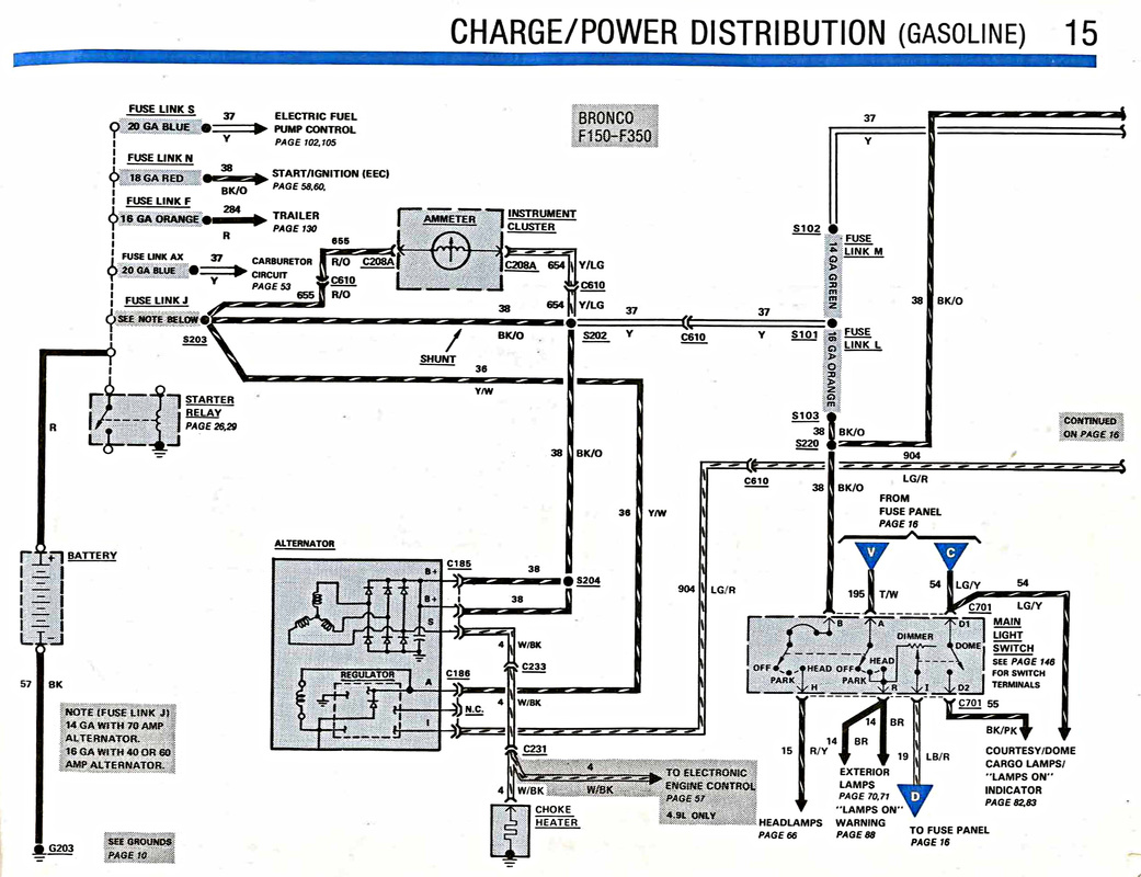
Gary, AKA "Gary fellow": Profile
Dad's: '81 F150 Ranger XLT 4x4: Down for restomod: Full-roller "stroked 351M" w/Trick Flow heads & intake, EEC-V SEFI/E4OD/3.50 gears w/Kevlar clutches
|
| Edit this page |

