Fuel Tank Selector/Pump Circuits
|
Hola ladies and gents, I have a couple questions that are probably really dumb...but here I am about to ask them. For context, I have a 1983 F-100 XLT LWB 2WD with dual gas tanks and I am trying to consider how I will set up my dual tanks for use with the return style Holley Sniper EFI. It has a regulator built in for those who aren't familiar with it.
I am not sure if I will do this immediately, but I have some spare time and I'm bored. I think long term it would be wise to go with this plan. I intend to travel hauling a Mustang on a trailer, up to 5 hours away. I really don't want to be stranded in another state not able to make it to the track, all because the 13 year old getting paid fifty cents an hour to build a fuel pump in a distant country was having a bad day. With this setup, I could simply switch to the other tank and keep driving. Hopefully the person who built that pump was having a better day and I can get home.
Further context: The Sniper has a fuel pump relay and fuse built into it's wiring harness. It has one blue wire coming out that can feed a fuel pump up to 20A. I want to use that wire, because then the Sniper can prime the pump for 5 seconds, automatically shut it off if the engine dies, etc.. This will keep me from having to wire in a separate fuel cutoff using oil pressure, etc. And I don't particularly want to just have a toggle switch.
(The Sniper does have the ability to run a second fuel pump, BUT that is intended as an aux pump for when the power levels exceed the capability of a single pump. It kicks in at certain RPM or TPS levels (don't recall which offhand). Won't work cleanly for dual tanks I don't think.)
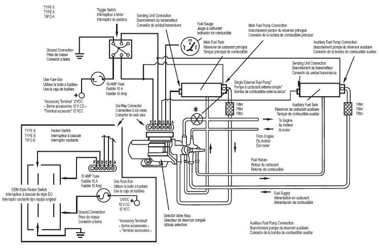
OK, so the part I really need help with: I am trying to decipher these pinouts on this fuel tank selector valve.
I used to think I was decent at doing that. I spent two years studying automotive in high school and another two studying engineering in college. I would think I could figure this out. But this manufacturer has the weirdest wiring diagram for this tank selector I have ever seen. Or maybe it's just late and my brain isn't firing on all cylinders. It doesn't really help that this style tank selector is set up to do a whole lot more than the one in my 83, which currently uses 1 wire.
ALL I want to have the selector switch do is flip the supply and return lines back and forth at the same time. I don't want to accidentally pull fuel from the front tank and then return it to the full rear tank and overflow it. I do NOT want to have the fuel tanks OR sending units wired into it. I want to leave those in their factory locations and NOT slice the wiring harness up inside the dash. It's all original right now (except the radio).
Essentially, I want the single wire that currently goes to the selector valve to operate two single pole double throw (SPDT) relays.
When the factory tank switch is moved to the auxilliary tank, the coils on the relays are energized.
That can be seen (hopefully) on the rough wiring diagram I made below...obviously it isn't finished, since I don't know which wire off the selector valve to use. You can see the spot I am questioning inside the big red circle with the question marks. Also, it's been too long for me to remember the symbols for everything lol. So hopefully it's understandable enough. It makes sense to me...but of course it would, I knew what I was thinking when I made it.
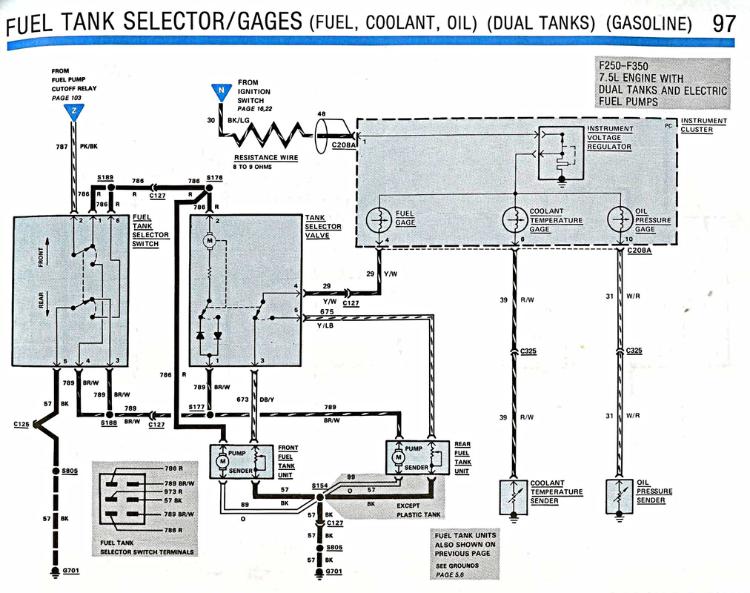
Aside from the question and problem above, does anyone see any glaring issues with my plan here? I don't know too much about this circuit. I am going off the 1985 year model wiring diagrams, also, but I would assume the 1985 and 1983 have fairly similar setups in regards to the Fuel Tank Selector Switch wiring? Thanks in advance, yall!
Chris S.
Little Rock, AR 1983 Ford-F100 XLT 2WD LWB 300 I6/C6 Auto/8.8", 3.55s A/C, Power Windows/Locks/Brakes Currently getting some much-needed TLC... |
Re: Fuel Tank Selector/Pump Circuits
|
Administrator
|
This post was updated on .
That's just how the 7.5l Hot Fuel Handling is set up.
I'm not sure what you're asking. You want the pinout for the tank selector valve? Have a look at how the relay works, on pg 105, here: http://www.garysgaragemahal.com/electric-fuel-pump-control1.html
Jim,
Lil'Red is a '87 F250 HD, 4.10's, 1356 4x4, Zf-5, 3G, PMGR, Saginaw PS, desmogged with a Holley 80508 and Performer intake. Too much other stuff to mention. |
|
In a nutshell, I want to put +12VDC into one pin on the 6 pin and connect another pin to ground and have it actuate and switch tanks.
Which pin gets +12VDC? Which pin should go to ground?
Chris S.
Little Rock, AR 1983 Ford-F100 XLT 2WD LWB 300 I6/C6 Auto/8.8", 3.55s A/C, Power Windows/Locks/Brakes Currently getting some much-needed TLC... |
Re: Fuel Tank Selector/Pump Circuits
|
Administrator
|
Which switch valve do you have?
Look at the diagrams in the EVTM applicable to your truck, or to the switch valve you want to use. All the harness color codes are clearly shown in those diagrams. At the end of each chapter is a synopsis, outlining functions, and differences between them.
Jim,
Lil'Red is a '87 F250 HD, 4.10's, 1356 4x4, Zf-5, 3G, PMGR, Saginaw PS, desmogged with a Holley 80508 and Performer intake. Too much other stuff to mention. |
|
I posted the wiring diagram of the one I want to use above.
Just having trouble deciphering it. I’ve dug into the diagrams, but can’t find what I want. Nothing seems to match this aftermarket one.
Chris S.
Little Rock, AR 1983 Ford-F100 XLT 2WD LWB 300 I6/C6 Auto/8.8", 3.55s A/C, Power Windows/Locks/Brakes Currently getting some much-needed TLC... |
Re: Fuel Tank Selector/Pump Circuits
|
Administrator
|
And which exactly is "this aftermarket one"
One of the Pollak valves marketed by 20 other companies? I apologise.  It's hard for me to get my head around your diagrams on my phone.
Jim,
Lil'Red is a '87 F250 HD, 4.10's, 1356 4x4, Zf-5, 3G, PMGR, Saginaw PS, desmogged with a Holley 80508 and Performer intake. Too much other stuff to mention. |
Re: Fuel Tank Selector/Pump Circuits
|
Administrator
|
This post was updated on .
In reply to this post by GimpyHSHS
Ok, that top diagram is the Pollak valve without question.
This is applicable to 42-151, -153, -159, & -1595 valves. The 42-203 connector is wired as: A) #1 sender B) gauge C) #2 sender D) #2 pump E) #1 pump F) empty So while your relay is feeding E)#1 or D)#2, the other one sees ground. Ground and power switch back and forth Take the top diagram and replace the DPDT switch with two relays.... or keep the stock switch.
Jim,
Lil'Red is a '87 F250 HD, 4.10's, 1356 4x4, Zf-5, 3G, PMGR, Saginaw PS, desmogged with a Holley 80508 and Performer intake. Too much other stuff to mention. |
|
I can't keep my stock switch, unfortunately. It's single wire, 3 port, and it doesn't have the ability to split the return line, meaning I would only be returning to a single tank. More problems if I have the return plumbed to the front tank and was using the rear tank, for example, especially if I went ahead and stopped and refilled the front tank...big mess. Plus, the system would be returning a lot more fuel than it's using (or at least, the Mustang does), so I would drain the rear tank really fast and need to switch back to the front tank. Not ideal and definitely not "right".
I hope I am understanding you right, but essentially, all I need to do is switch both wires from positive to negative and negative to positive simultaneously. I wasn't grasping that initially. I think that's easy to do with a DPDT relay operated off my current positive wire. Take a look and let me know your thoughts here please.
Chris S.
Little Rock, AR 1983 Ford-F100 XLT 2WD LWB 300 I6/C6 Auto/8.8", 3.55s A/C, Power Windows/Locks/Brakes Currently getting some much-needed TLC... |
Re: Fuel Tank Selector/Pump Circuits
|
Administrator
|
I guess I'm confusing switch with valve?
Yes, your latest schematic should work just fine with that Pollak valve.  I'm not sure why you don't simply use a switch from a diesel or 7.5 that is a crosswired dpst as shown in the initial drawing. And why you have the senders wired through the switch rather than the valve. But that must have been the way a 300 switch was wired. Although I hear about these Snipers here on the forum I've never dealt with one. And maybe my comprehension is not there because I haven't read the manual.
Jim,
Lil'Red is a '87 F250 HD, 4.10's, 1356 4x4, Zf-5, 3G, PMGR, Saginaw PS, desmogged with a Holley 80508 and Performer intake. Too much other stuff to mention. |
|
Whoops! I was really careful to get it right in the initial post, but, yeah, I meant "valve" in that last post.
Good to hear. I have senders wired through the switch (instead of the valve) because that's how the stock 83 switch is wired (I think). It's a DPDT switch, with senders wired through one pole, nothing on the normally closed (switch on the front tank) and the single 12v wire on the other normally open wire. At least, that's what the 1985 wiring diagram shows. I don't really want to go digging into the dash wiring to switch it to running through the valve. "I'm not sure why you don't simply use a switch from a diesel or 7.5 that is a crosswired dpst as shown in the initial drawing." I don't understand what you're saying here...I think the switch I am going with (the Standard Motor Products FV5), the same one I posted the wiring diagram to in the initial post, IS the replacement for those vehicles too. I don't find another switch out there for these.
Chris S.
Little Rock, AR 1983 Ford-F100 XLT 2WD LWB 300 I6/C6 Auto/8.8", 3.55s A/C, Power Windows/Locks/Brakes Currently getting some much-needed TLC... |
Re: Fuel Tank Selector/Pump Circuits
|
Administrator
|
This post was updated on .
Edit: I meant the manufacturer drawing... the first in this thread.
Let me call your attention to pages 97 & 98 of the '86 EVTM. http://www.garysgaragemahal.com/fuel-tank-selector--gauges1.html 
Jim,
Lil'Red is a '87 F250 HD, 4.10's, 1356 4x4, Zf-5, 3G, PMGR, Saginaw PS, desmogged with a Holley 80508 and Performer intake. Too much other stuff to mention. |
| Edit this page |


