Electrical Circuitry Clean Up - Circuit/Junction Box
|
Administrator
|
I’m about to install a PMGR starter and was evaluating the needed wiring changes for this particular upgrade. While it’s not much of a rewire, I’m really limited in where I can attach things to the starter relay. With the 3g alternator mod, headlight harness mod, and now the addition of the PMGR starter mod, I have very limited attachment area on my starter relay and frankly, it’s beginning to look like a rat’s nest! I like a clean and orderly looking set up and this is not it.
I know there are automotive circuit boxes out there that house relays and help to better organize circuits, but I wouldn’t know where to start with that. Hoping one of you electrical geniuses can pop in and advise? As said above, I’ve done the headlight harness mod which has two relays, but I’m good with where they are unless there is a better recommendation. I’ve also done the 3g alternator mod and you can see it’s related relay on the passenger side inner fender. I’m about to do the PMGR starter mod and I understand there is a mod done for the heater blower motor that requires a relay but not sure it is in close enough proximity to wire to some type of junction/circuit box. Aside from that, I’ll not be adding any other electrical components or additional electrical related mods to this truck. Thoughts on how to clean up my wiring mess would be much appreciated. Thanks!!! 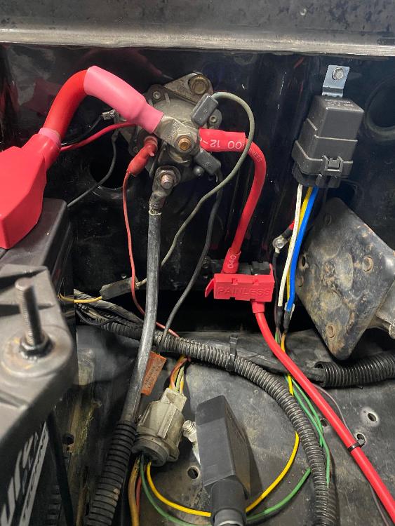 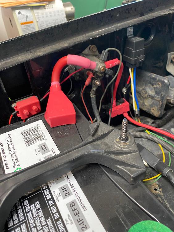
John
"Blackie" - 1986 F150 4x4 - Mildly warmed over 351W HO - Original owner |
|
Hey John,
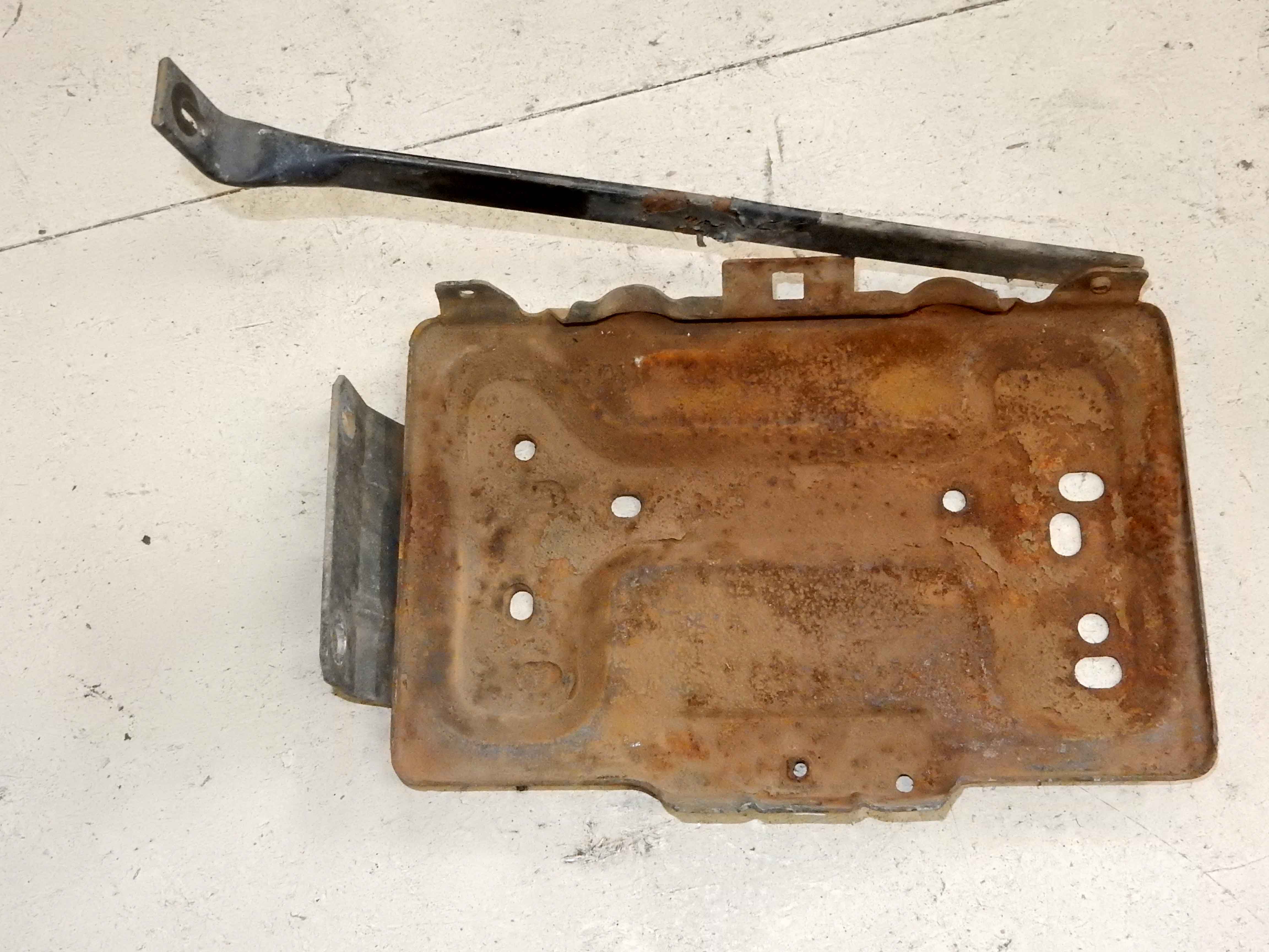
My 2 cents worth, but if you switched back to the Bullnose style starter relay (solenoid) it keeps the larger wires farther apart and would look neater imo. I know the newer solenoids are technically better, but with both main lugs on the front like that they are harder to keep tidy imo with the big cables.
1994 F150 4x2 Flareside. 5.0 w/MAF, 4R70W, stock.
1984 F150 4X2 Flareside. Mild 302 w/ 5spd. Sold. 1980 F150 4X4 Flareside. 300i6 w/ 5spd. Sold in 2021. 1980 F100 4X2 Flareside. 351w/2bbl w/NP435. Sold in 1995 |
|
Administrator
|
Cory, believe it or not, but that is the original OEM starter relay! I have noticed some differences between relays, and I thought about maybe going with a different relay to better accommodate all the wires and their orientation but wondering now if a good junction box would be better. I'm open for all options.
John
"Blackie" - 1986 F150 4x4 - Mildly warmed over 351W HO - Original owner |
Re: Electrical Circuitry Clean Up - Circuit/Junction Box
|
Administrator
|
In reply to this post by Machspeed
John - I like the PMGR starter. And to do it all you need to do is to move the black cable up to the top terminal and add the trigger wire to the starter on the now-vacant bottom terminal. And that's what I would do.
As for cleaning up, I see two approaches: Factory Box: There are several different Ford boxes available. I have a two-relay box and I'm pretty sure I have a 4-relay box. Plus, I have another 5-relay box just like the one that's going into BB right now. The two-relay box doesn't have fuses, but the 4-relay box might, and the 5-box certainly does. Plus, some of the larger boxes have a place for a megafuse.Aftermarket Box: Scott and some of the others are using aftermarket boxes and they have various numbers of fuses and relays. But I'm not a good source of info on those.Now, here's my take on it. You pride yourself in keeping your truck looking stock. What I would do is to add a Ford power distribution box with at least 5 relays, a megafuse, and several smaller fuses. I believe it will fit between the battery and the jack with the megafuse pointing toward the engine. Leave the fender-mounted relay in place to trigger the starter. But put the large battery cable and the large starter cable, as well as the alternator cable, on the megafuse. Move the headlight relays and voltmeter relays into the box, and add the one or two for the heater if you want. And use some of the fuse slots for fuses for the headlights and heater. It will look factory and only Bullnose aficionados will know the difference. And, I'll help you do it if you want - after I get Big Blue's EFI going.
Gary, AKA "Gary fellow": Profile
Dad's: '81 F150 Ranger XLT 4x4: Down for restomod: Full-roller "stroked 351M" w/Trick Flow heads & intake, EEC-V SEFI/E4OD/3.50 gears w/Kevlar clutches
|
|
Administrator
|
In reply to this post by Machspeed
My 86 also has that pig-nose (bullnose was taken
 ) style of fender mounted relay. I believe all my pre-86 have the uprights. ) style of fender mounted relay. I believe all my pre-86 have the uprights.
Good call on changing to the newer starter and as Gary said, the wiring for it won't add any mess or require other relays. For the other, I'll also second Gary and say that you'll be very happy with an enclosed relay/fuse box. Will be a perfect fit for keeping things clean like you want. While I am a huge fan of the ssVEC line, I also think a Ford unit would go with the look of your truck better than any aftermarket box. Gary (that's three times so I am waiting for him to appear beside me now) has some great diagrams in the BB thread that I'd print out and look over to see what is similar to what you are wanting. I suspect there will be quite a bit.
Scott
'Camano' 1986 F250 Supercab XLT Lariat 460/C6 'Chanute' 1980 F350 C&C 400/NP 435 - Gin Pole But there ain't nothin' wrong with the radio |
Re: Electrical Circuitry Clean Up - Circuit/Junction Box
|
Administrator
|
I’m here!
 Yes, I have some diagrams. But there are at least two styles of PDB - with and without megafuse. I think you want with, so let me see what I have tomorrow. They are easily rewired, so I don’t think it would be all that difficult. It is what I did on the right side of Big Blue.
Gary, AKA "Gary fellow": Profile
Dad's: '81 F150 Ranger XLT 4x4: Down for restomod: Full-roller "stroked 351M" w/Trick Flow heads & intake, EEC-V SEFI/E4OD/3.50 gears w/Kevlar clutches
|
|
In reply to this post by kramttocs
Well look at that, I had no idea. I guess from trolling the junkyards, I thought that style relay didn't come out until after the Bullnose. I even thought it was way later, like 1992-1996.
1994 F150 4x2 Flareside. 5.0 w/MAF, 4R70W, stock.
1984 F150 4X2 Flareside. Mild 302 w/ 5spd. Sold. 1980 F150 4X4 Flareside. 300i6 w/ 5spd. Sold in 2021. 1980 F100 4X2 Flareside. 351w/2bbl w/NP435. Sold in 1995 |
Re: Electrical Circuitry Clean Up - Circuit/Junction Box
|
Administrator
|
In reply to this post by kramttocs
I did Darth's conversion to a PDC (Power Distribution Center) about 10 years ago. It was driven by the need to change the under hood wiring to allow EFI and an E4OD in place of the Holley 4180C and miles of vacuum line, dual air pumps etc. and add the overdrive and lock up converter in place of the C6.
I had started with the front end harness from the 1990 F250 parts truck as I was changing the front sheet metal due to Darth's previous owner parking by feel. The 1990 truck still had a 2G alternator and a clump of fusible links which I wanted to get rid of as some had already been patched. I also wanted to change the dash as Darth's had the usual cracks and the top pad was crumbling where the single speaker went. I had done part of the work toward installing the 1990 dash and steering column as it is very similar. The area that gave me a problem was the left side kick panel area. Ford moved the EEC from just to the right of the steering column to the left air box area by indenting the side of the airbox so the EEC fit without requiring a bulge in the left kick panel. First issue, parking brake attachment to firewall and dash wouldn't match up no matter what, so back to the drawing board. I had already extended the chassis harness by the 35" difference between a std cab 8' bed and a crew cab 8' bed when I was looking at a 1995 truck and realized the differences. Dash and steering column presented the biggest issue, but the PDC and wiring could have been used without the inside changes. One item, on a Bullnose, the main electrical feed runs from the fusible link "nest" all the way across inside the cab and comes out on the left side to a power stud. It could easily be fed from the PDC on that side, or that could be used to feed a PDC. To get the full benefit, you would still need to remove the branches off the large yellow wire and bring them out to the PDC.
Bill AKA "LOBO" Profile
"Getting old is inevitable, growing up is optional" Darth Vader 1986 F350 460 converted to MAF/SEFI, E4OD 12X3 1/2 rear brakes, traction loc 3:55 gear, 160 amp 3G alternator Wife's 2011 Flex Limited Daily Driver 2009 Flex Limited with factory tow package Project car 1986 Chrysler LeBaron convertible 2.2L Turbo II, modified A413 |
Re: Electrical Circuitry Clean Up - Circuit/Junction Box
|
Administrator
|
John - I'll make this two posts to answer the questions in our phone call this morning.
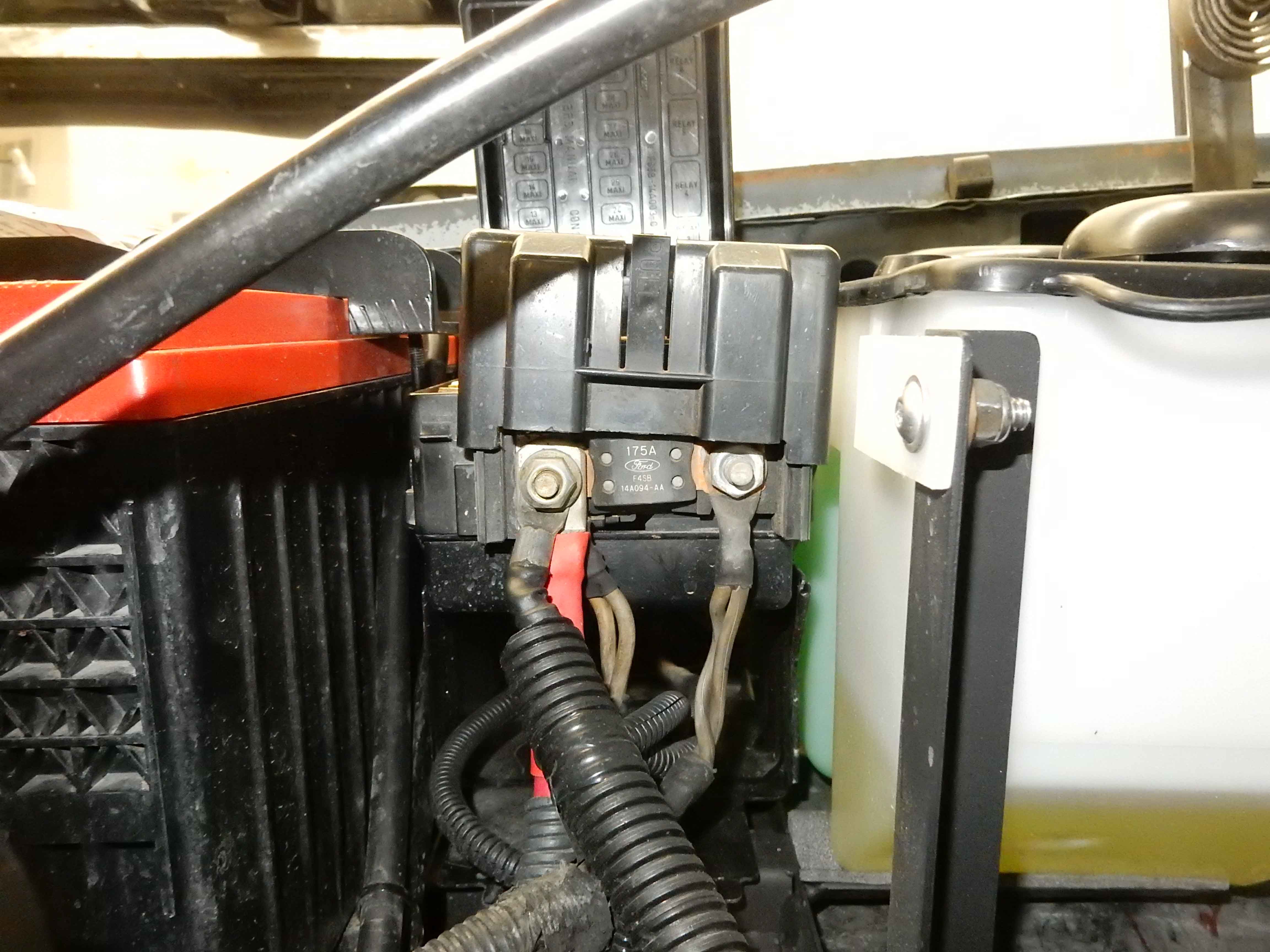
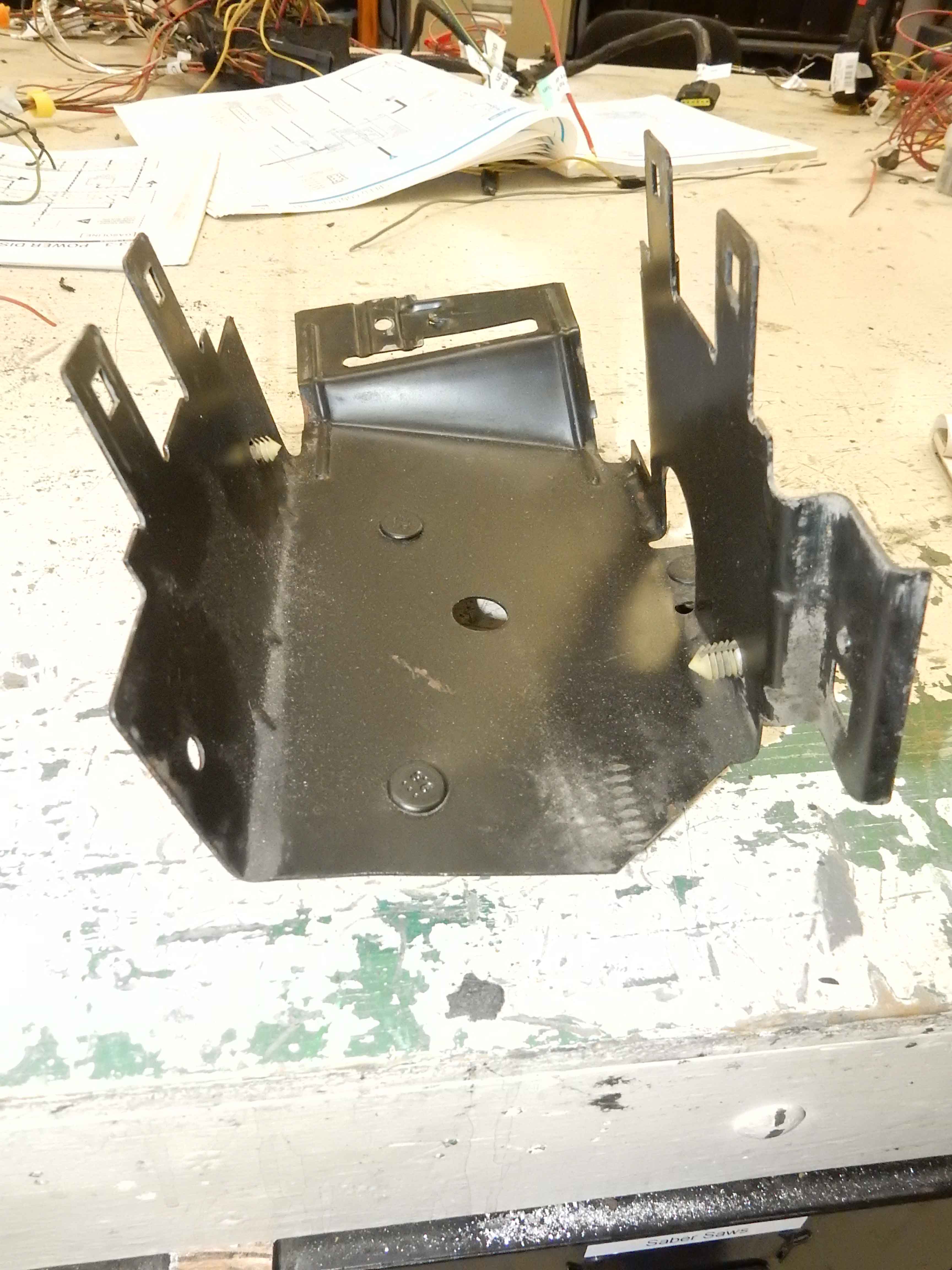
First, Here are a couple of shots Big Blue's large PDB on the passenger's fender. It is one of the mid-90's F-Series PDB's I mentioned. HOWEVER, it has the place for a megafuse on the inboard end, and the other PDB's I have that size don't. So if you want one that size you'll have to scout the salvages. But, as said, this one didn't have both studs for the megafuse, just one stud and a place for the other and I added the 2nd stud. The others I have do not have the place for the 2nd stud so won't work for what you want to do. 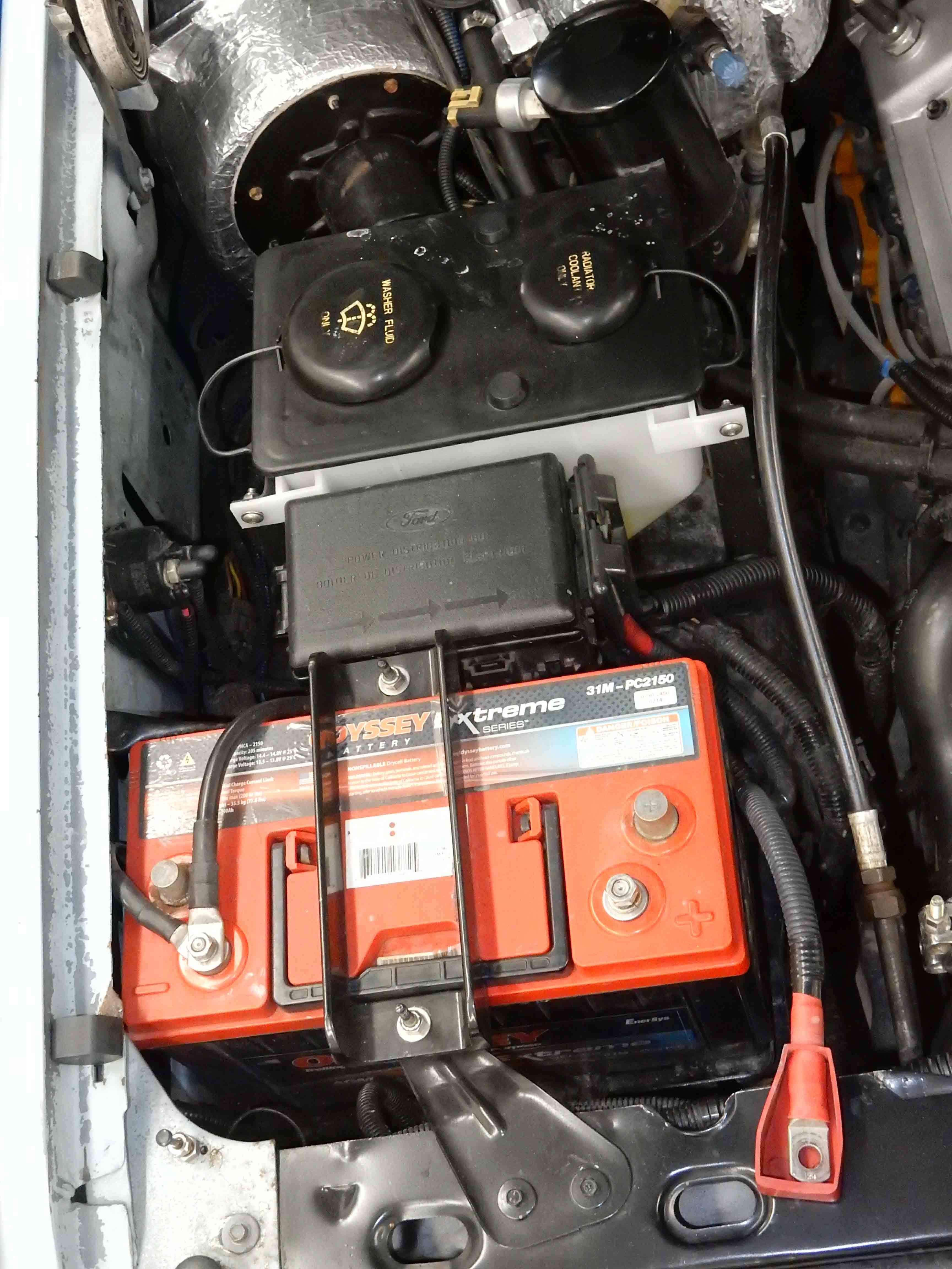 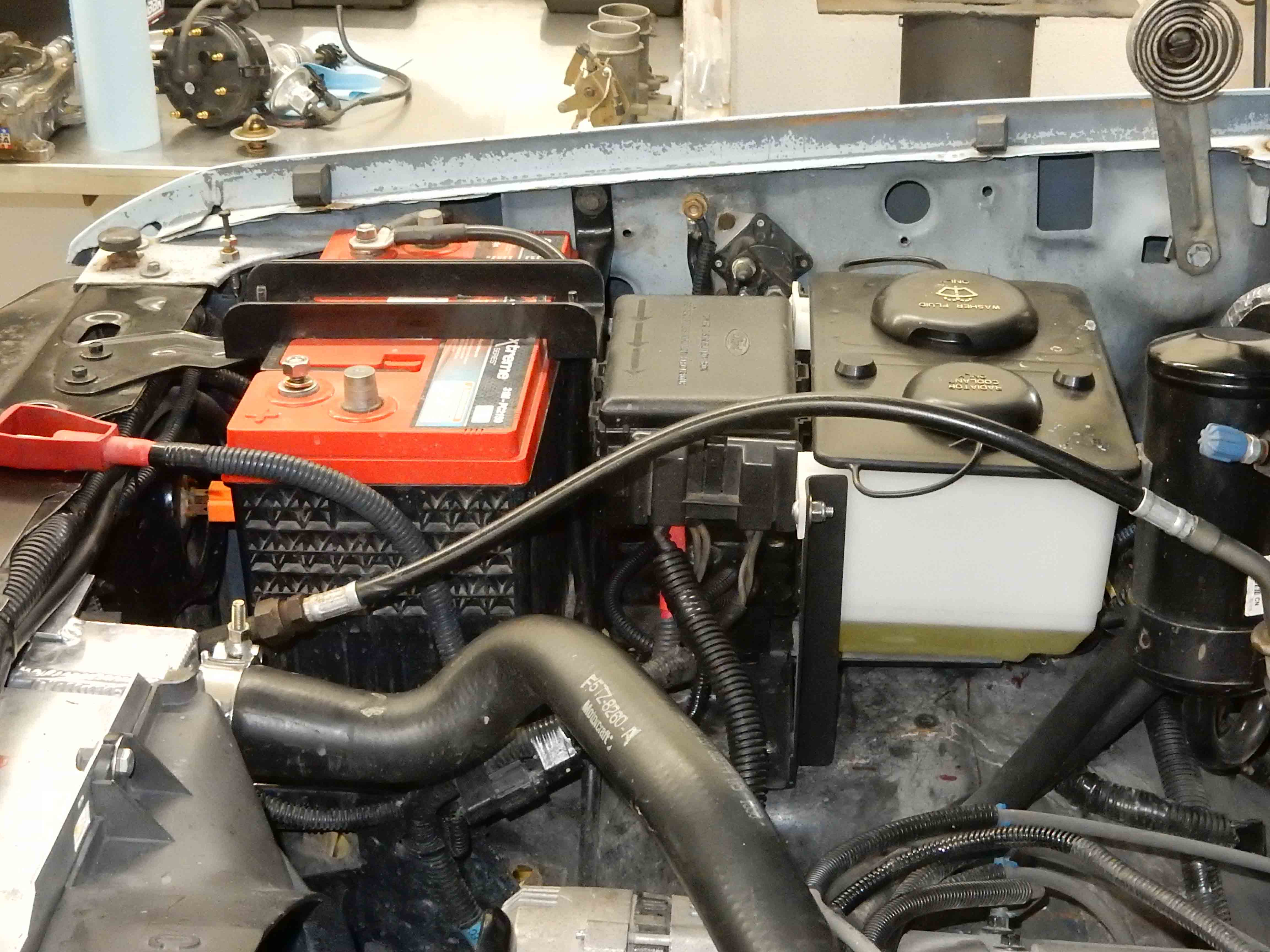 However, this one will work and it is smaller. It is from Ford but the top doesn't say that.  However, it has the place for the megafuse, although someone robbed the 2nd stud from it. However, it has the place for the megafuse, although someone robbed the 2nd stud from it.  And, it has places for 6 relays, and while only 3 of them are the larger relays, the smaller ones can still handle 20A if I remember correctly, so they'd be fine for things like the headlights and voltmeter, and you could use a couple of the larger ones for the heater motor. And, it has places for 6 relays, and while only 3 of them are the larger relays, the smaller ones can still handle 20A if I remember correctly, so they'd be fine for things like the headlights and voltmeter, and you could use a couple of the larger ones for the heater motor.
It is yours if you want it, and it would be easy to fit in between the battery and the jack. It is 4" wide & 10" long, and while the larger 5-relay box is shorter at 8" it is also wider at 5" so could be slightly harder to get in there. Still, either can be made to fit pretty easily. 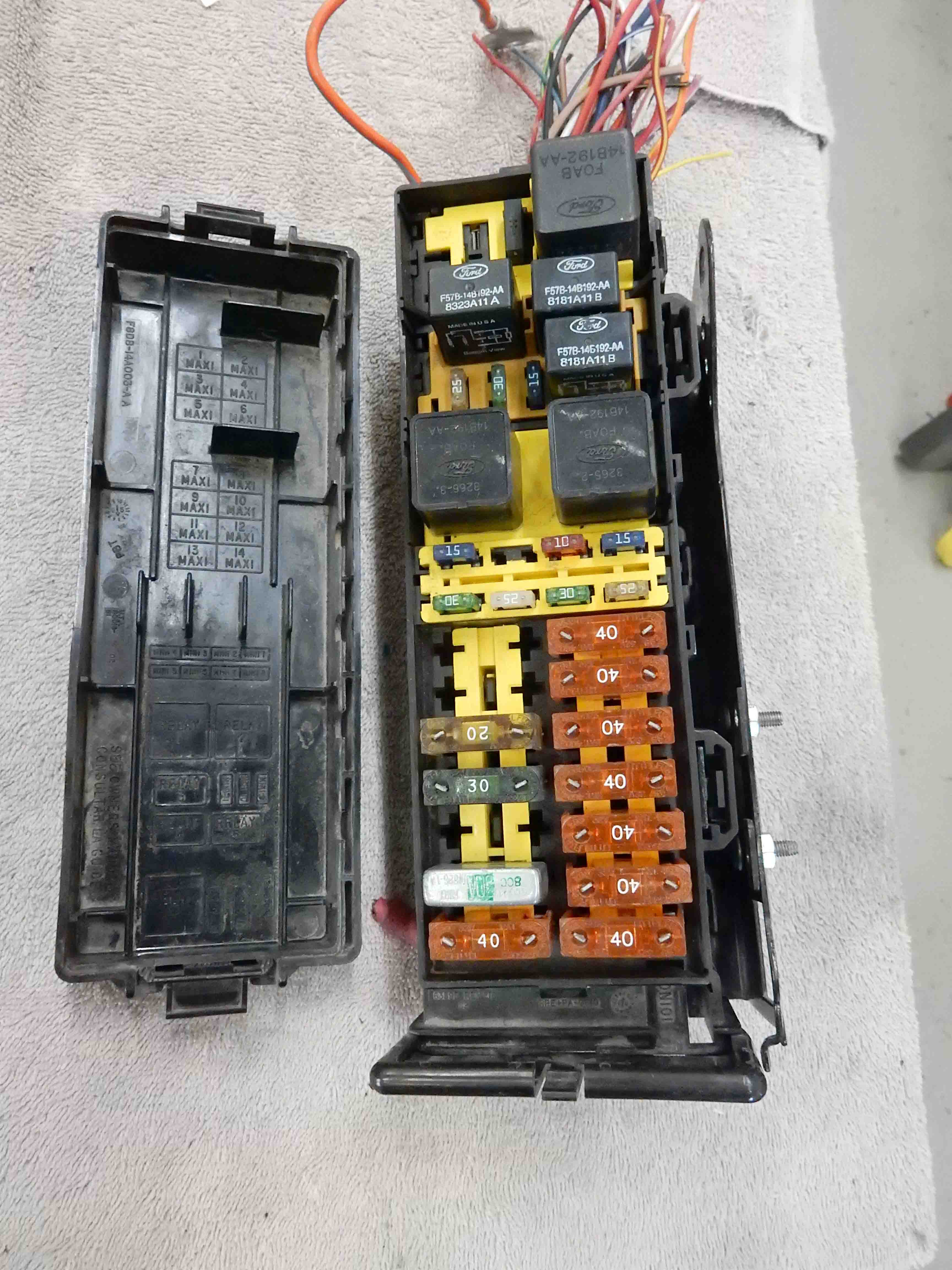 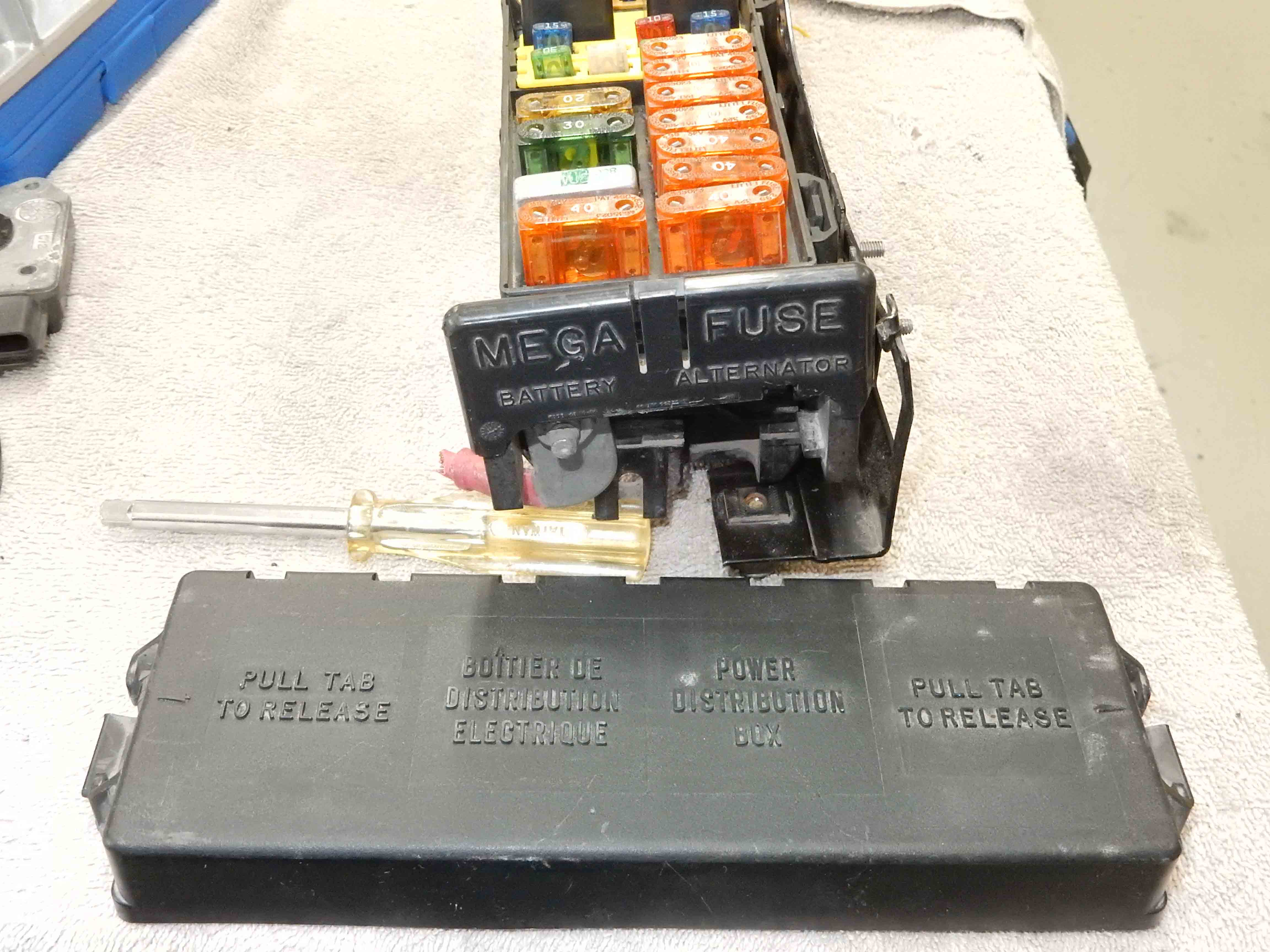
Gary, AKA "Gary fellow": Profile
Dad's: '81 F150 Ranger XLT 4x4: Down for restomod: Full-roller "stroked 351M" w/Trick Flow heads & intake, EEC-V SEFI/E4OD/3.50 gears w/Kevlar clutches
|
Re: Electrical Circuitry Clean Up - Circuit/Junction Box
|
Administrator
|
And you asked for wiring diagrams. But first, I need to confess that I just remembered that BB's passenger side PDB is a 6-relay model. So if you go looking for one like it you need to know that.
And it has 3 large and 3 small relays. They number from 1 on the right to 6 on the left, and as you'll see below I've used a small relay for the low beams and a large relay for the high beams. The thinking was that I might go with bulbs that have a higher wattage on the highs, hence the larger relay. 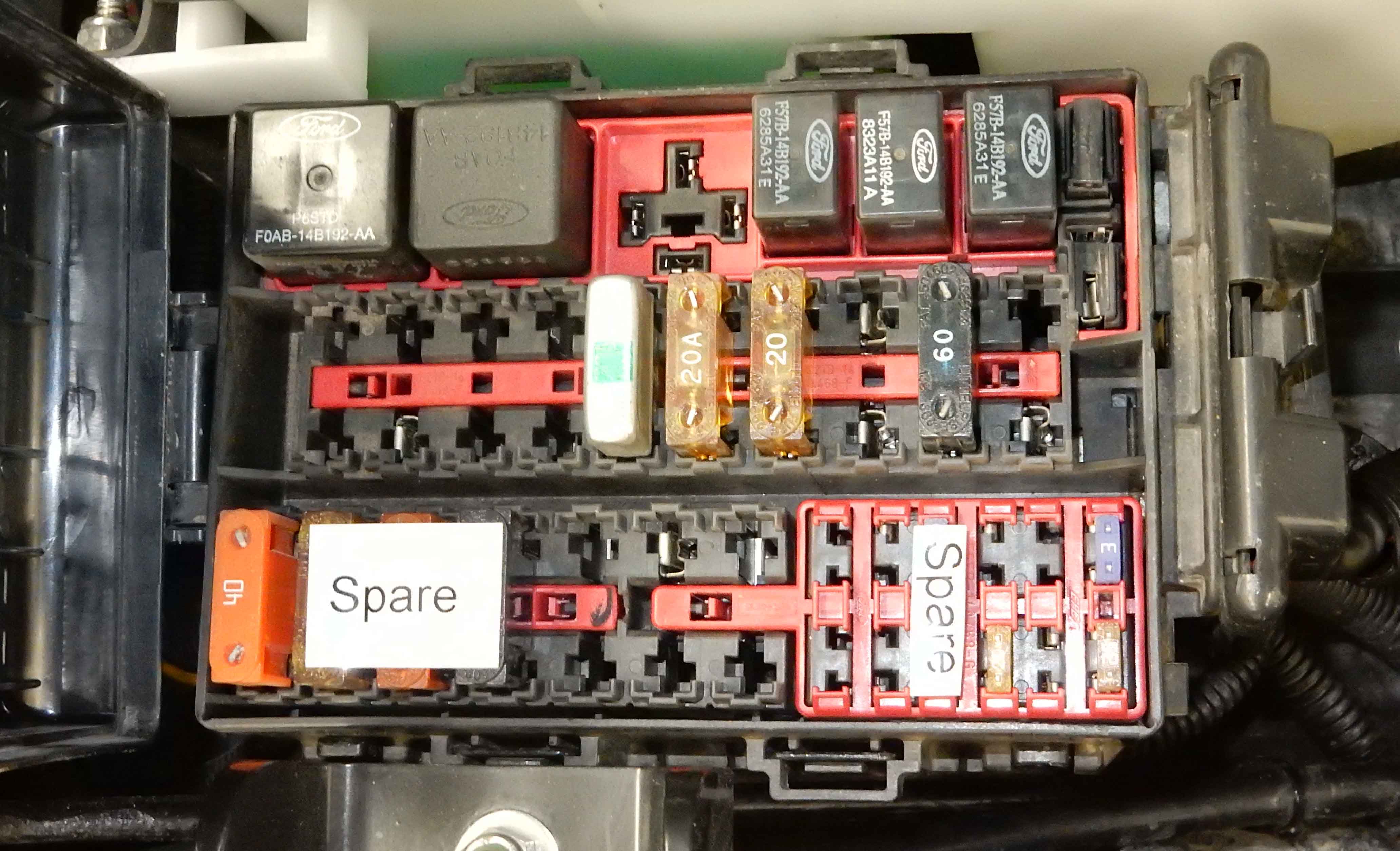 Anyway, here's the diagram. And even though it was "printed" at 600 dpi it is hard to read, so here's a link to the same thing as a pdf, and it can be easily read. However, this diagram is out of date and needs to be revised as it still shows powering the starter from a Bosch relay, and that is no longer the case - as we discussed. PS_PDB_Wiring.pdf 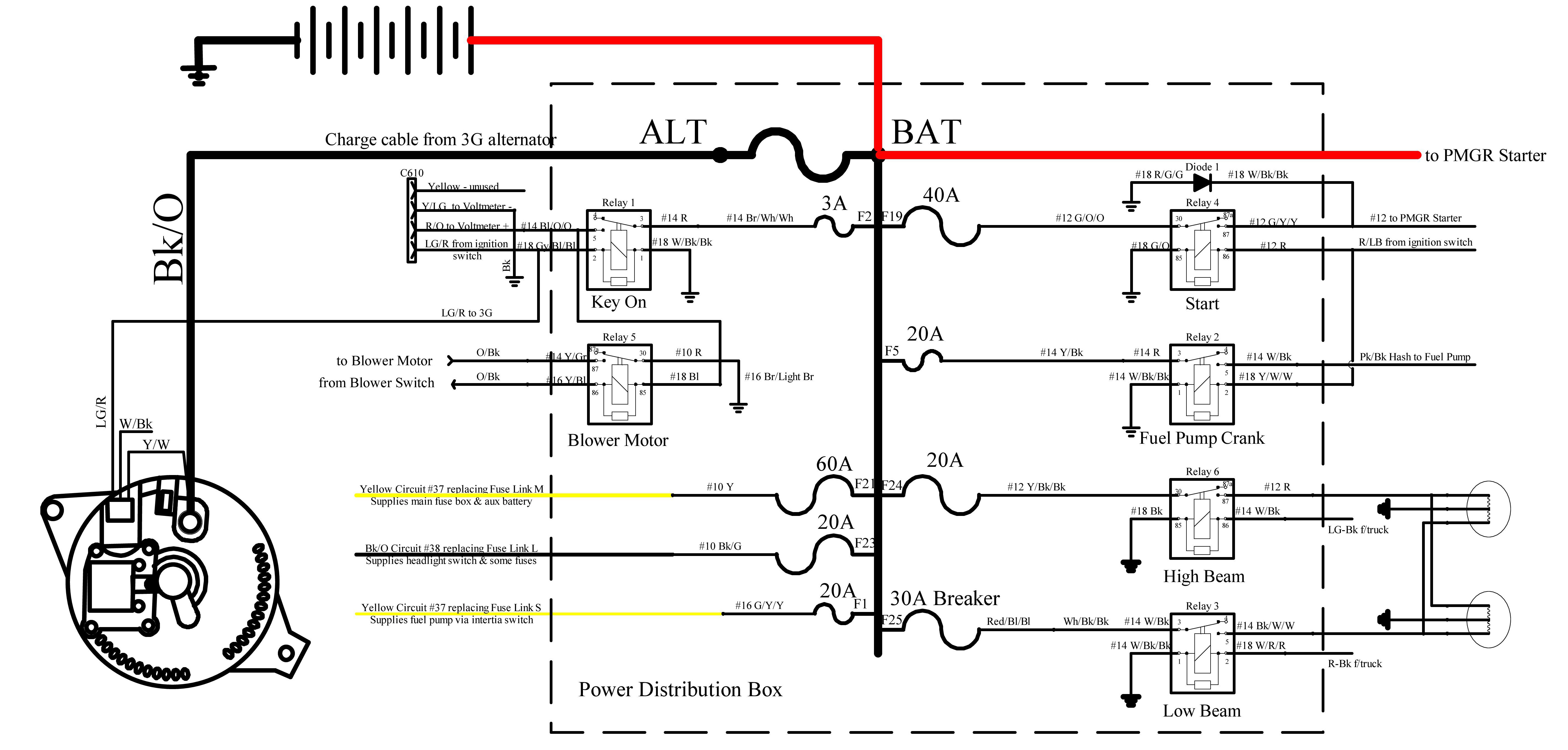 Similarly, here's the EFI PDB. And here's the link to the pdf:EFI_PCB_Wiring.pdf. 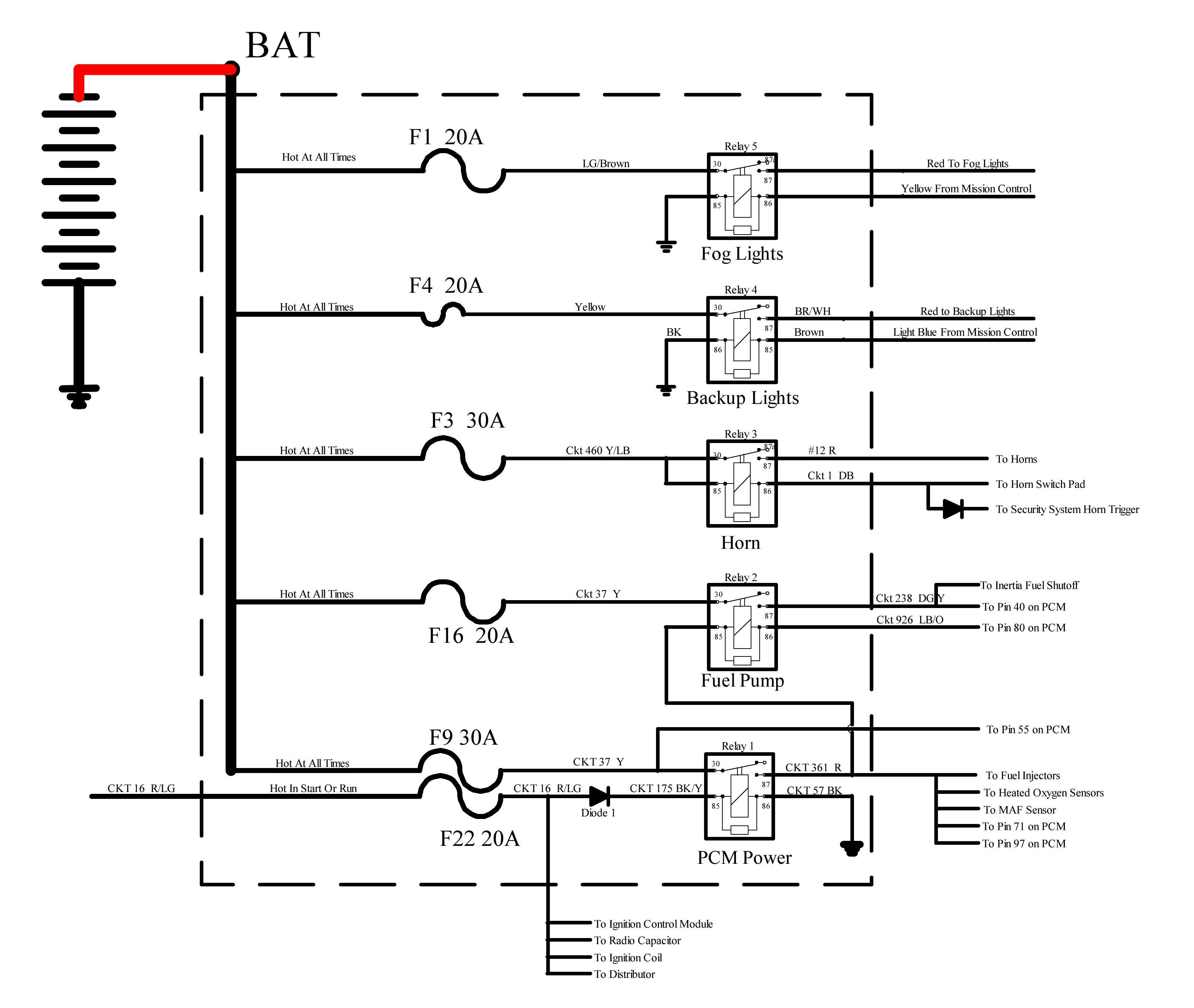 Last, while I don't have a drawing for the narrow 6-relay PDB we can easily do that. 
Gary, AKA "Gary fellow": Profile
Dad's: '81 F150 Ranger XLT 4x4: Down for restomod: Full-roller "stroked 351M" w/Trick Flow heads & intake, EEC-V SEFI/E4OD/3.50 gears w/Kevlar clutches
|
|
Administrator
|
In reply to this post by Gary Lewis
Thanks a bunch, Gary! I need to study this a little bit, will likely have questions.
John
"Blackie" - 1986 F150 4x4 - Mildly warmed over 351W HO - Original owner |
Re: Electrical Circuitry Clean Up - Circuit/Junction Box
|
Administrator
|
You know where I live and how to reach me.

Gary, AKA "Gary fellow": Profile
Dad's: '81 F150 Ranger XLT 4x4: Down for restomod: Full-roller "stroked 351M" w/Trick Flow heads & intake, EEC-V SEFI/E4OD/3.50 gears w/Kevlar clutches
|
Re: Electrical Circuitry Clean Up - Circuit/Junction Box
|
Administrator
|
I got the following questions from John/Machspeed last night via email and got his concurrence to answer them here. John's questions are in red and my answers in black.
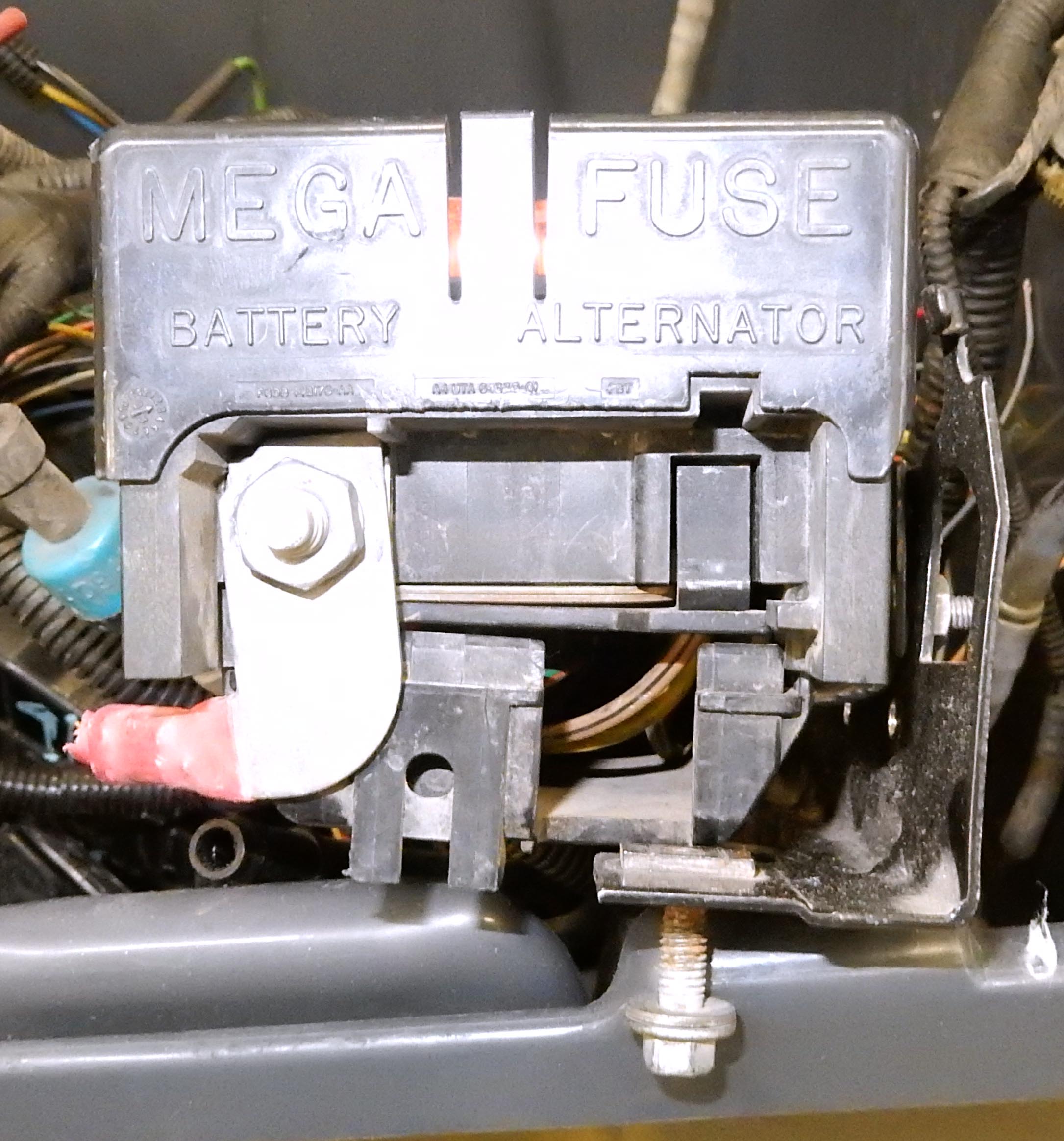 And here's a shot of Big Blue's megafuse in the passenger-side PDB:
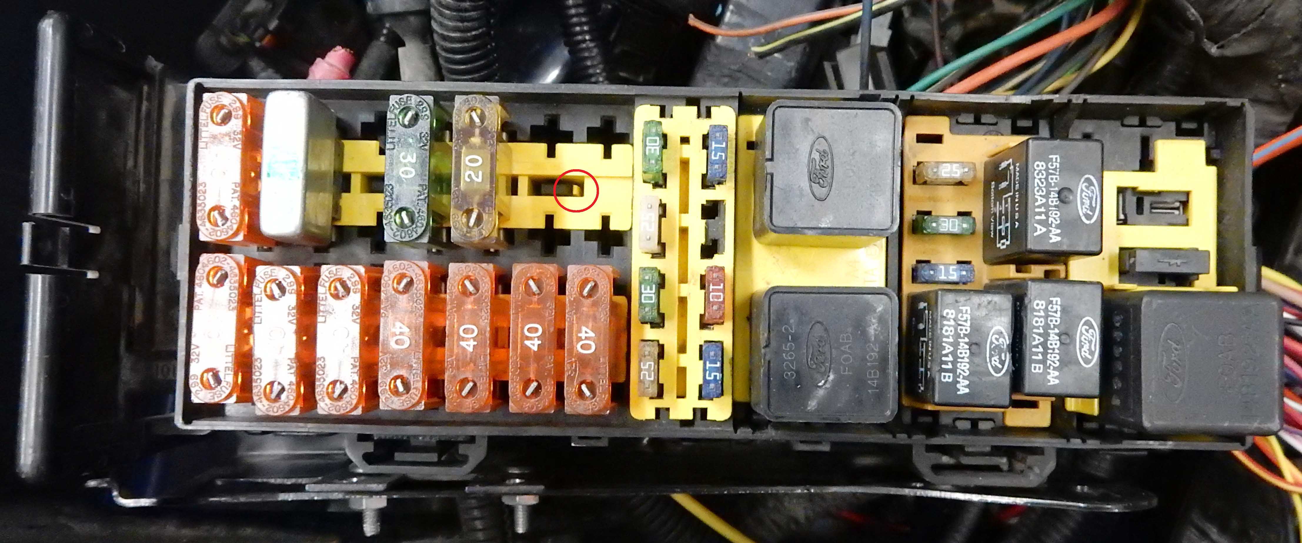
 Now let's talk about removing the terminals. In this shot of the slim PDB you can see the retainers - they are the yellow plastic pieces. Each of the retainers has a couple of clips that hold it in, and I've circled in red one of them in this pic.
 Here's a shot of one of the 5-relay PDB's with the relay retainer pulled up. You can see the clips that hold it in on each end of it.
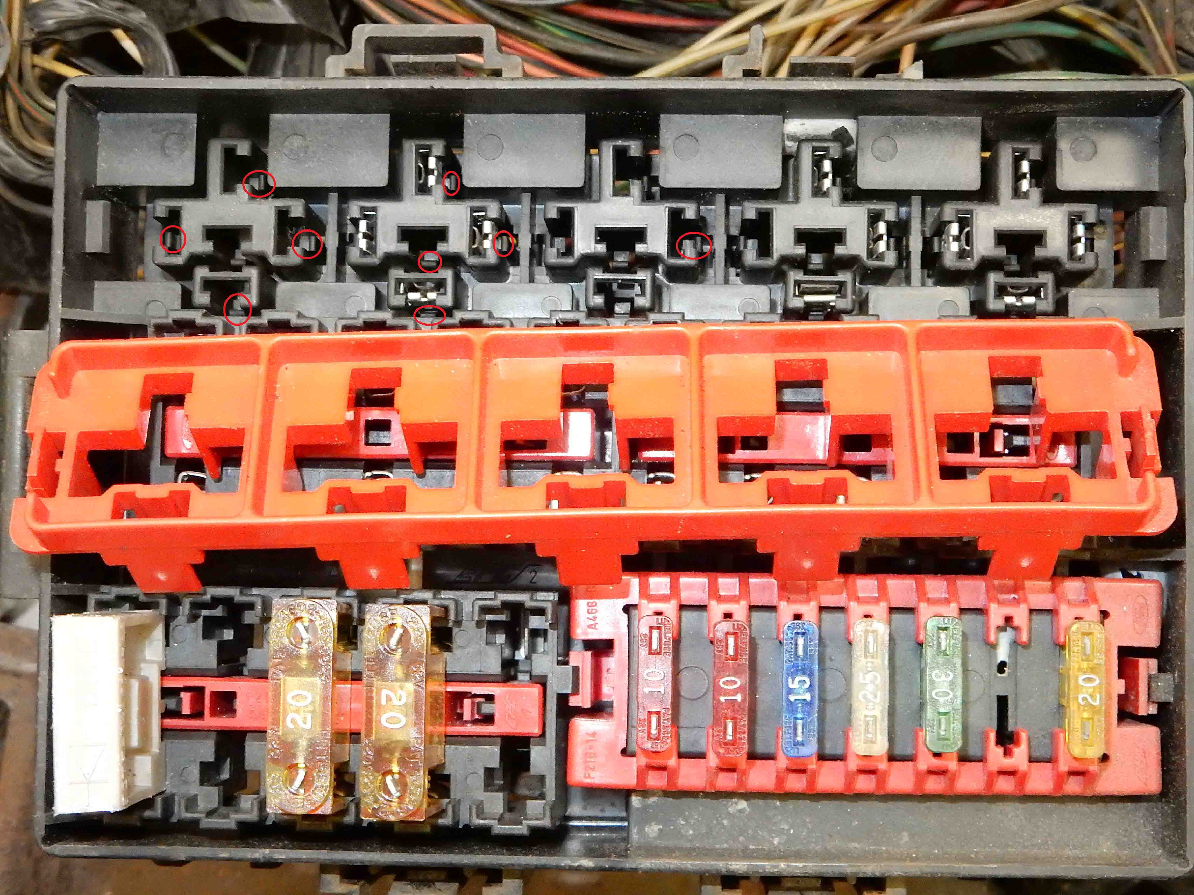
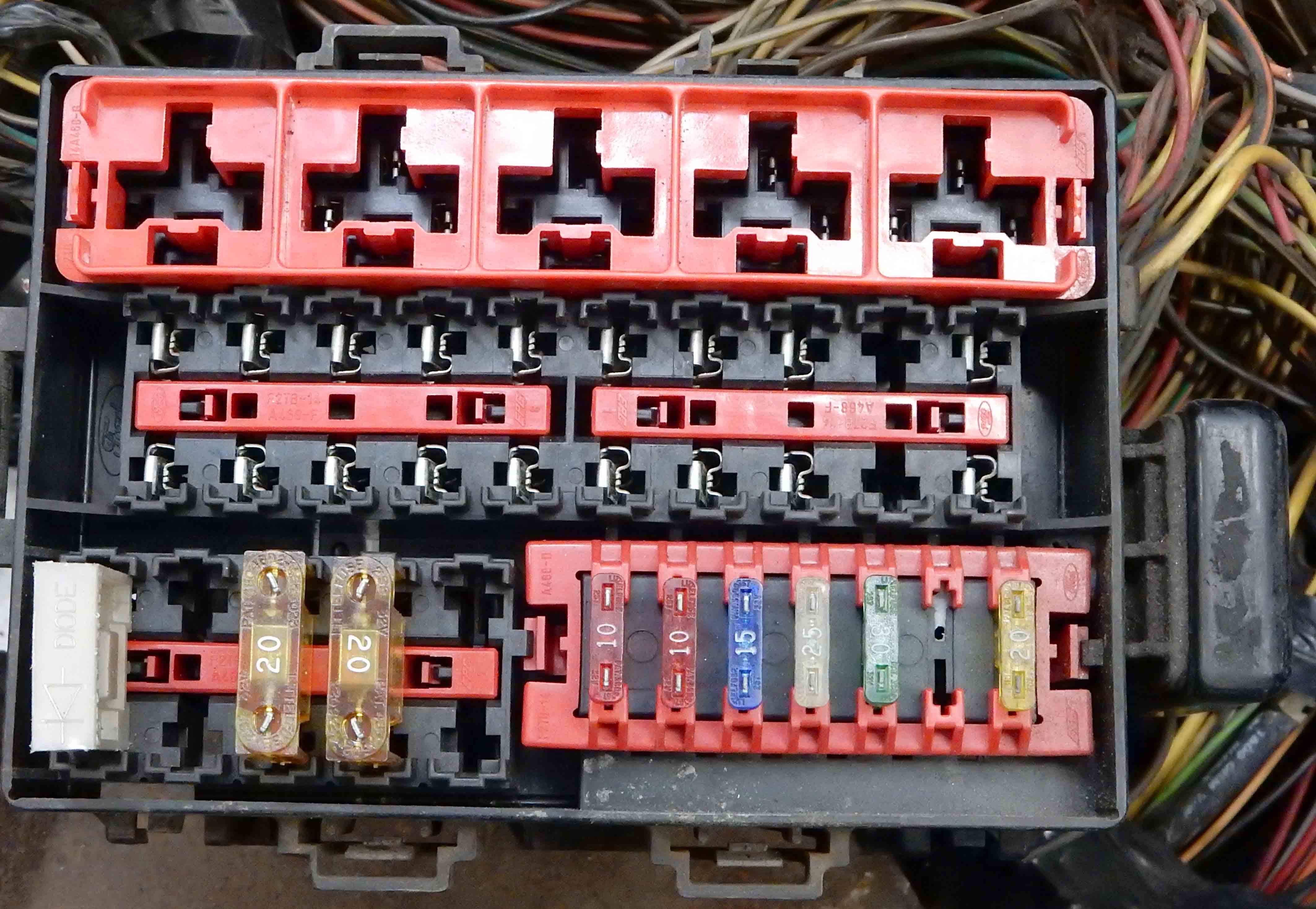 And in this pic of the same 5-relay PDB I've circled some of the retaining clips that hold the terminals in the box. You can't get to those clips w/o pulling that red retainer, and you'll break the clip if you try to put a terminal in w/o pulling the retainer. (Don't ask.)
Gary, AKA "Gary fellow": Profile
Dad's: '81 F150 Ranger XLT 4x4: Down for restomod: Full-roller "stroked 351M" w/Trick Flow heads & intake, EEC-V SEFI/E4OD/3.50 gears w/Kevlar clutches
|
|
Administrator
|
Do you happen to have a photo of one of the terminals removed?
Scott
'Camano' 1986 F250 Supercab XLT Lariat 460/C6 'Chanute' 1980 F350 C&C 400/NP 435 - Gin Pole But there ain't nothin' wrong with the radio |
Re: Electrical Circuitry Clean Up - Circuit/Junction Box
|
Administrator
|
Yes. Thanks for asking.
 Oh, you want to see one? Ok. These pics show a maxifuse connector on the left and a standard fuse connector on the right. But in the pic on the right you can see the tabs that stick out and make sure that you orient the terminal the right way. And if you don't know they are there it can be frustrating. And you can also see the slot in the smaller terminal where the retainer pin locks it in. 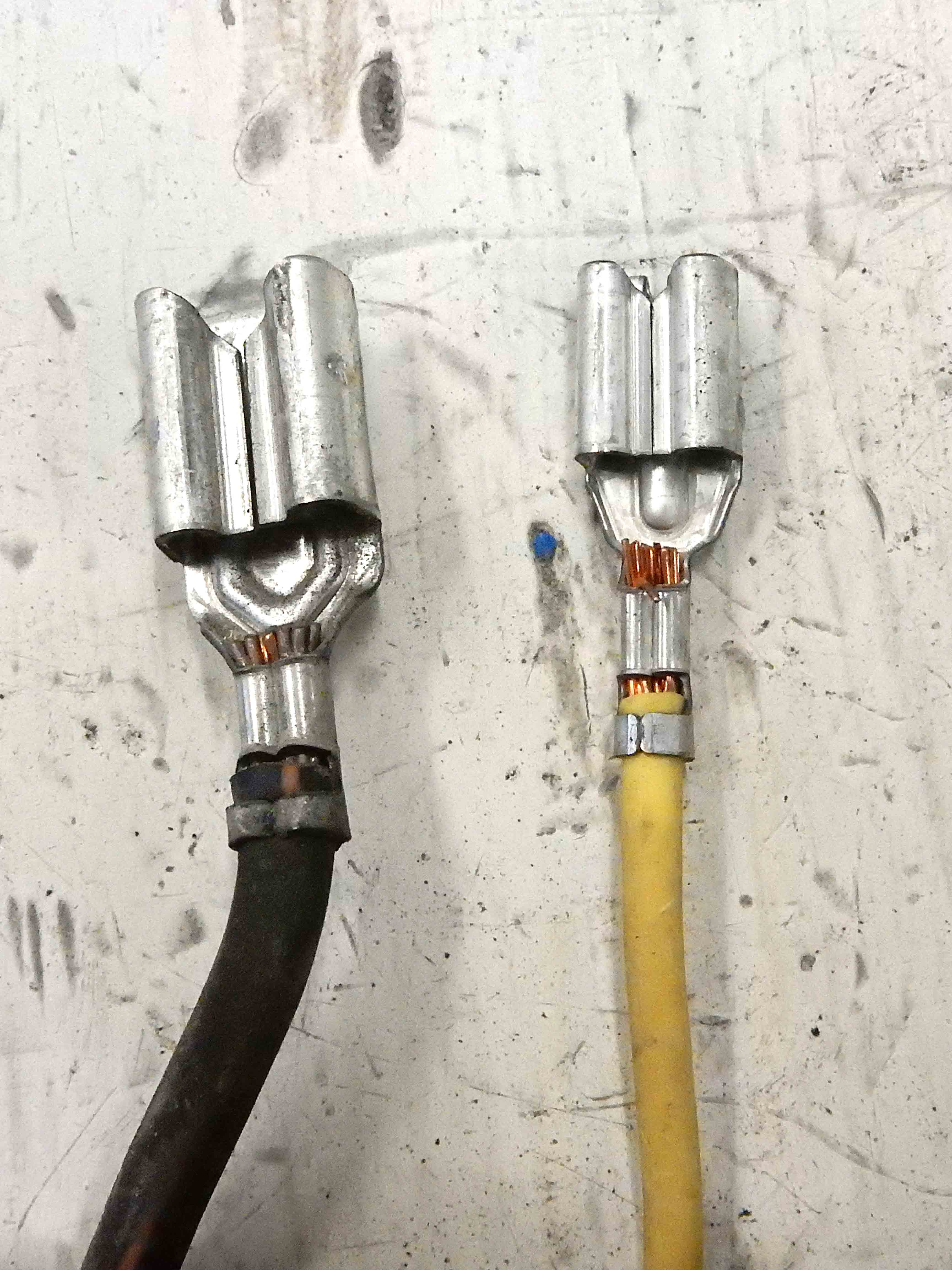 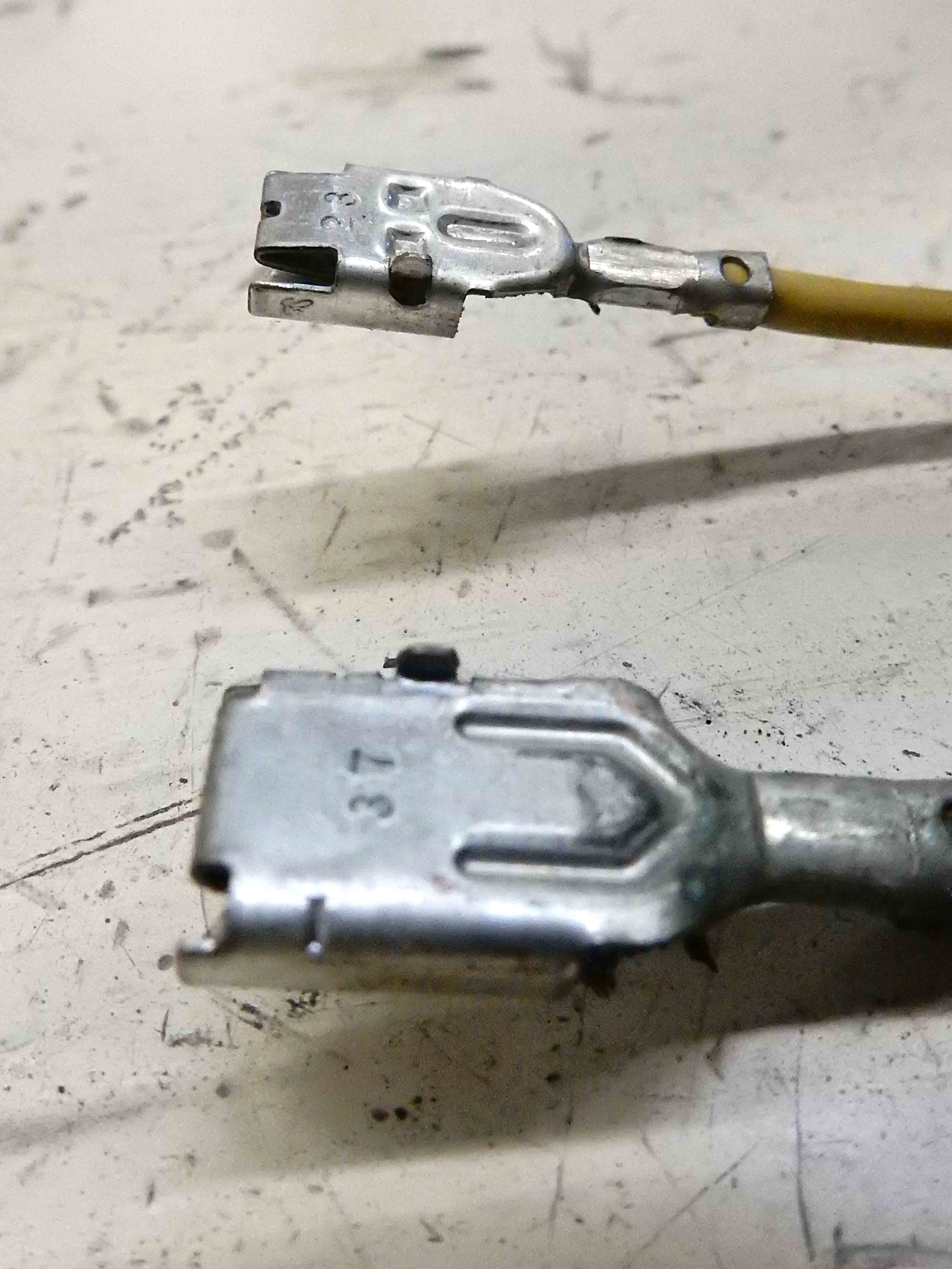
Gary, AKA "Gary fellow": Profile
Dad's: '81 F150 Ranger XLT 4x4: Down for restomod: Full-roller "stroked 351M" w/Trick Flow heads & intake, EEC-V SEFI/E4OD/3.50 gears w/Kevlar clutches
|
Re: Electrical Circuitry Clean Up - Circuit/Junction Box
|
Administrator
|
And, John/Machspeed asked a few more questions via email. But I'll post here to preserve the answers for posterity. (But I've edited his questions slightly to make it easier to answer.) My answers are in bold.
Questions:
Gary, AKA "Gary fellow": Profile
Dad's: '81 F150 Ranger XLT 4x4: Down for restomod: Full-roller "stroked 351M" w/Trick Flow heads & intake, EEC-V SEFI/E4OD/3.50 gears w/Kevlar clutches
|
|
Administrator
|
Gary, thanks for all this! I went ahead and ordered the PBD through ebay. Keeps Scott from telling his wife he needs to go to the salvage yard. She will be pleased! And Scott, also found the steering shaft, no trips for you....

Gary, are those connectors available? Not sure yet if I want to de-pin and run new wires or just solder in to the existing wires. What would you do? BTW, I saw you were looking for a schematic on these boxes at FTE sometime back, did you ever find it? Thanks fellas!!!
John
"Blackie" - 1986 F150 4x4 - Mildly warmed over 351W HO - Original owner |
Re: Electrical Circuitry Clean Up - Circuit/Junction Box
|
Administrator
|
Welcome. I hope the PDB is the one you want.
As for the terminals, I've not found them by themselves. I just reuse them, but not by removing the wire as it looks well and truly IN THERE. So I solder to the original wire down the way a bit. And, I indicated that on my schematic with a dot and show the two wire colors either side of the dot. But I've never found a schematic for them. I've just made my own.
Gary, AKA "Gary fellow": Profile
Dad's: '81 F150 Ranger XLT 4x4: Down for restomod: Full-roller "stroked 351M" w/Trick Flow heads & intake, EEC-V SEFI/E4OD/3.50 gears w/Kevlar clutches
|
Re: Electrical Circuitry Clean Up - Circuit/Junction Box
|
Administrator
|
In reply to this post by Machspeed
Ford will show pieces of the PDB, on the 1996 the main distribution is several pages and the engine type (gas or Diesel) makes a difference also. You have to know which parts go through it, Horn, EEC power, Fuel Pump, power feed to the ignition switch, headlight switch etc.
It's probably the one place I think Chrysler did a better job. Section 8 (appropriate for any military veterans) is electrical, 8W is wiring diagrams. 8W-10 is under hood PDC, 8W-12 is inside fuse box, 8W-15 is ground distribution.
Bill AKA "LOBO" Profile
"Getting old is inevitable, growing up is optional" Darth Vader 1986 F350 460 converted to MAF/SEFI, E4OD 12X3 1/2 rear brakes, traction loc 3:55 gear, 160 amp 3G alternator Wife's 2011 Flex Limited Daily Driver 2009 Flex Limited with factory tow package Project car 1986 Chrysler LeBaron convertible 2.2L Turbo II, modified A413 |
|
Administrator
|
In reply to this post by Gary Lewis
There you go again Gary, cluttering up the site with helpful photos
 Thanks for those - looked in the usual places and couldn't find a match on the terminals. Just like the ones for the Bullnose fuse box, looks like these weren't provided separately. John - Glad to hear you found both! Though I might still use your name as an excuse to make a trip... Gary and I both found when adding circuits to the factory fuse box that removing the crimped wires was futile. For a few I was able to pull strands out one at a time, pry the ears, and slip a new wire in there but like Gary said - soldering is the best option. Could also see how far one can put shrink wrap up the terminal (over the new solder) without it being too bulky to fit into the box.
Scott
'Camano' 1986 F250 Supercab XLT Lariat 460/C6 'Chanute' 1980 F350 C&C 400/NP 435 - Gin Pole But there ain't nothin' wrong with the radio |
| Edit this page |

