Search Forum
Drivers door power lock
|
Morning All, I finally Took off my driver side door panel to address a door lock issue. At first I was thinking that it was going to be more of a switch and bezel issue, but now I’m starting to think that the actual power lock mechanism inside the door at the bottom might have failed and I am not sure what the best way to test this is without removing it first which seems like a pain in the butt. If I push the switch/lever on the drivers door only the passenger door activates. If I push the switch/lever on the passenger door only the passenger door activates. In my mind this suggests that the driver side door switch/liver is functioning unless it is somehow interrupting the transfer of electrical signal to the power lock. I was fiddling around with that yesterday to try to essentially connect across the switch as if there was no switch and the locks would always be electrified( just for a second) to try to test my theory that the switch might somehow be interrupting transfer of signal But so far no luck. Before I try to remove the power lock, could it be as simple as a lose wire? Any other thoughts or options? I’ve got the schematic although I seem to have a few more pink unlabeled wires than the schematic mentions

Christopher in Portland Or. 1981 F250 Ranger XLT 4x4 trailer special 351M, and auto C6
|
|
Administrator
|
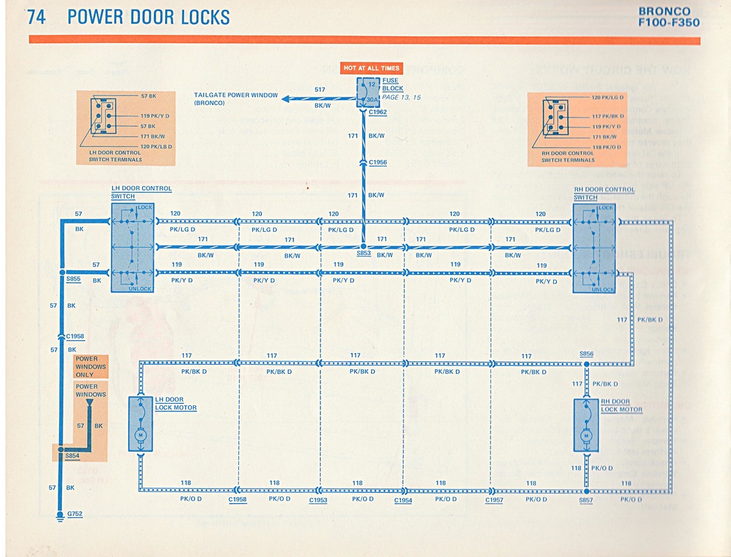
Are you using the schematic here? Documentation/Electrical/EVTM/1981 EVTM/Power Door Locks. As shown below.
You should be able to pull Connector 1958 apart, or any of the many others, and hit the pink/orange wire with ground and the pink/black wire with FUSED power and get the lock to go one way. Then reverse the leads and make it go the other. 
Gary, AKA "Gary fellow": Profile
Dad's: '81 F150 Ranger XLT 4x4: Down for restomod: Full-roller "stroked 351M" w/Trick Flow heads & intake, EEC-V SEFI/E4OD/3.50 gears w/Kevlar clutches
|
|
Banned User
|
In reply to this post by delco1946
The circuit is deceptively complicated... Each switch assembly is really 2 electrically-interconnected (but not mechanically) SPDT switches. The 2 assemblies are mostly in series, but their hot supplies are parallel. Each internal switch is normally closed to the other assembly so that everything is held to ground. When either switch is activated, one internal switch disconnects from ground, and connects to hot. If the driver's switch is activated, then all 4 of the internal switches (2 in each assembly) are used; if the passenger switch is activated, then only 3 are used. But the lock MOTORS are strictly in parallel. What happens to one always happens to the other. So if either lock motor works, the other is getting power (assuming no open circuits in the harness going back to the driver's motor) to do the same thing. Here are some more diagrams that might make it easier to unnerstan:   Ignore the bottom of the 2nd one. Again - not a simple as you might expect, and it depends which switch you want to bypass. It's much simpler to just power & ground the motor wires from the passenger switch connector (after removing the switch). Using a small 12V battery (as from a cordless tool) is easier than trying to jumper the connector to use the truck battery. It doesn't really matter how long you do it - the motors have internal thermal circuit breakers, but they're designed to tolerate being powered for several seconds at a time. |
|
Sorry for the slow response, went to Seattle for the weekend! This is very helpful, hopefully I’ll take a look before the weekend as I’m getting tired of my interior constantly being disassembled for “something”.

Christopher in Portland Or. 1981 F250 Ranger XLT 4x4 trailer special 351M, and auto C6
|
Bullnose Enthusiasts Forum
|
1 view|%1 views
| Edit this page |

