Search Forum
C325 questions
|
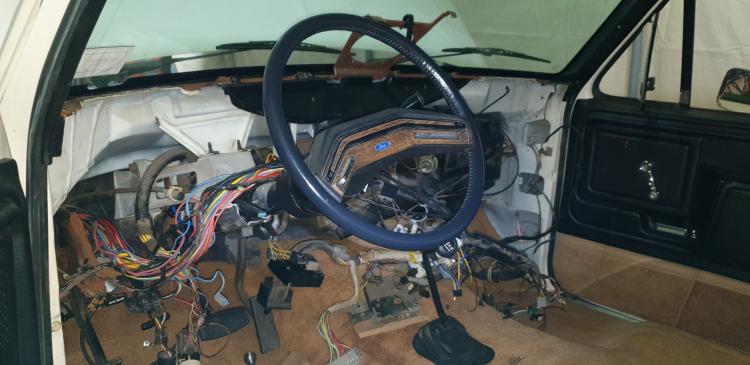
Now that the old 300 is out of the bay, I thought that I’d take the opportunity to tidy up things a bit. I have been diagnosed with a very severe case of the “while I’m in there, I might as well” desease!
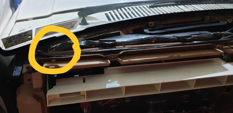
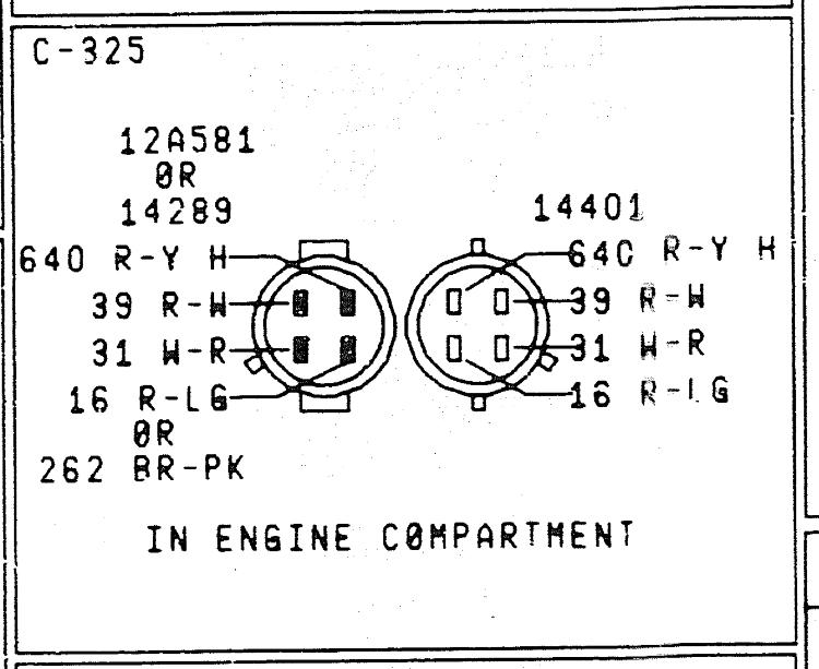
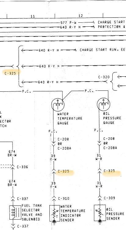
Thanks to Jeff’s post about the C322 connector and the other two, C321 & C323, I’ve decided to make all new mini harnesses to all of the connections between the firewall and the engine. That brings me to something that I can’t stop wondering about. C325 connects the firewall harness to three things on my engine; + side of the coil Oil pressure sensor for the gauges Water temp sensor for the gauges What I can’t seem to get my head around is that the R/LG wire on the harness side is LARGE I’m guessing AWG 10? And then on the engine side of C325 the R/LG is more like a 14-16 AWG Why? I’m used to sizing wires in residential construction based on anticipated amperage. If that thinking carries over to automotive DC wiring, then Ford must have imagined a large load on that R/LG wire. But then they connected it to a MUCH smaller wire @C325. As long as you’ve read this far I’ll ask another question. I’ve seen mentioned that the EVTMs and the wiring diagrams (schematics) indicate color/ circuit/ wire size. I’ve never been able to see ANYWHERE an indication of wire size. Am I missing it somewhere? Has anyone else ever seen wire size?
Kurt K
'85 XLT Lariat, ‘95 4.9L, Sniper 2300 on an Offy C, ‘97 4R70W w/ Quick 4, 3.08LS, DSII, 130a 3G, PMGR, '87 MC, P235/R75 |
|
Administrator
|
You need to look in the front of the book.
If you don't have a physical copy, I can't recommend enough that you find a used one on eBay for around $25. Evidently I'm going to have to pull up the '85 and paste the pertinent pages in this thread. That might take a while but I should have time on the overnight.
Jim,
Lil'Red is a '87 F250 HD, 4.10's, 1356 4x4, Zf-5, 3G, PMGR, Saginaw PS, desmogged with a Holley 80508 and Performer intake. Too much other stuff to mention. |
|
Thanks Jim,
I’ve had a physical hard copy of the 1985 EVTM as well as the factory service manuals builders book, c size prints of the schematics, etc. for years now and that’s probably where it says that gauge is indicated. I just have never seen a demarcation that would indicate gauge.
Kurt K
'85 XLT Lariat, ‘95 4.9L, Sniper 2300 on an Offy C, ‘97 4R70W w/ Quick 4, 3.08LS, DSII, 130a 3G, PMGR, '87 MC, P235/R75 |
|
In reply to this post by Tarheel Blue
Is R/LG the one that goes to the coil positive ? I wonder if the larger gauge wire is part of / continuation of the resistance wire. Also, is there actually more conductor or just more insulation ?
Vivek
- BB 2WD - 1984 F350 RWD 460/C6 - 1978 Bronco with a 460 from an 86 Bullnose/C6 |
|
That’s an interesting question, but I don’t know yet as I’ve not snipped it off at the connector. Might should do that in the morning. And yes, it connects to the much smaller wire that ends at the coil horseshoe.
Kurt K
'85 XLT Lariat, ‘95 4.9L, Sniper 2300 on an Offy C, ‘97 4R70W w/ Quick 4, 3.08LS, DSII, 130a 3G, PMGR, '87 MC, P235/R75 |
|
Well, that snipping is sort of irreversible, I am not sure you need to do that :) Those old wires don't like to be soldered back, and you will need to use heat shrink crimp fitting to get it back together.
My best guess is that it is one of the idiosyncrasies of the wiring. If you have a current clamp meter, might be a good idea to see how much current is flowing through the positive coil R/LG wire while running.
Vivek
- BB 2WD - 1984 F350 RWD 460/C6 - 1978 Bronco with a 460 from an 86 Bullnose/C6 |
|
Administrator
|
https://forum.garysgaragemahal.com/Pre-Emptive-FIRE-tp58908.html
 
Jim,
Lil'Red is a '87 F250 HD, 4.10's, 1356 4x4, Zf-5, 3G, PMGR, Saginaw PS, desmogged with a Holley 80508 and Performer intake. Too much other stuff to mention. |
|
Thanks. That’s a good recall of that wire being discussed… So it does look to be the resistor wire or at least an extension of it. Also.. the reason for the heat on it is power dissipation through the resistance wire, and therefore a bit more insulation to keep things protected? That makes it look like a lower gauge wire.
Vivek
- BB 2WD - 1984 F350 RWD 460/C6 - 1978 Bronco with a 460 from an 86 Bullnose/C6 |
|
Administrator
|
I think it's almost like a fusible link, with an insulation that won't burn.....
Jim,
Lil'Red is a '87 F250 HD, 4.10's, 1356 4x4, Zf-5, 3G, PMGR, Saginaw PS, desmogged with a Holley 80508 and Performer intake. Too much other stuff to mention. |
|
Administrator
|
In reply to this post by viven44
Total recall, it's my Superpower! 🤣
Jim,
Lil'Red is a '87 F250 HD, 4.10's, 1356 4x4, Zf-5, 3G, PMGR, Saginaw PS, desmogged with a Holley 80508 and Performer intake. Too much other stuff to mention. |
|
In reply to this post by ArdWrknTrk
Agreed
Vivek
- BB 2WD - 1984 F350 RWD 460/C6 - 1978 Bronco with a 460 from an 86 Bullnose/C6 |
|
In reply to this post by ArdWrknTrk
It a valuable gift, but also, I'm sure it is a function of interest in subject. Wife says I don't recall anything that I don't want to

Vivek
- BB 2WD - 1984 F350 RWD 460/C6 - 1978 Bronco with a 460 from an 86 Bullnose/C6 |
|
Administrator
|
I'm constantly, painfully, aware of sounds, smells, textures, and anything incongruous.
I can hear a stumble or a lifter clacking from blocks away. It's a blessing, and a curse. It's a function of CPTSD and autism....
Jim,
Lil'Red is a '87 F250 HD, 4.10's, 1356 4x4, Zf-5, 3G, PMGR, Saginaw PS, desmogged with a Holley 80508 and Performer intake. Too much other stuff to mention. |
|
In reply to this post by Tarheel Blue
I have the same question. Am I missing something, or there is no clear answer for now? Even the wiring diagram has no mention about the wires gauges (or I don’t understand how to read at it?)   
Jeff / 1984 F350 Crew Cab 4x4/5.8L w351 4V/ T18/ D50 4.10 front/ 8' bed.
Restored 2019-2022. Nicknamed «Big Brother 1984», due to its soooo-looong shape & nod to George Orwell's 1984 famous novel. |
|
I’m guessing for now it simply remains one of life’s unsolved mysteries.
But it does segue nicely into another question that I have moving forward on the design and fabrication of some harnesses. Because of future added devices, Sniper TBI, Quick4 TCM, etc. I’m in the need to find wires to tap into for “Hot in Run” and “Hot in Start & Run” I’ve identified which wires to tap into/ splice into in the existing harness in the engine bay. My question becomes; How often can I splice into one wire? My concern falls back to my residential wiring knowledge of sizing wire based on amperage of device and/ or distance to device. But I have no idea the rated amps of either the device that the existing wire is serving nor the rating of the devices that I’d like to add to the circuit. Where do I go from here in laying out my new harnesses?
Kurt K
'85 XLT Lariat, ‘95 4.9L, Sniper 2300 on an Offy C, ‘97 4R70W w/ Quick 4, 3.08LS, DSII, 130a 3G, PMGR, '87 MC, P235/R75 |
|
Administrator
|
Get yourself a little 6 position fused relay box, like I did
You can choose whatever key on source you like. (If it's going near the battery I suggest the LG/R alternator excite wire) Use it to trigger relays. They only pull a few milliamps. Set up as many fused & relayed circuits as you need.
Jim,
Lil'Red is a '87 F250 HD, 4.10's, 1356 4x4, Zf-5, 3G, PMGR, Saginaw PS, desmogged with a Holley 80508 and Performer intake. Too much other stuff to mention. |
|
That’s a great idea and one to think seriously about.
But I still like to learn and therefore the question remains. How does one determine the draw of individual devices when the whole engine bay is disassembled/ inoperable? I’m in the design/ fabricate phase. Is there info somewhere short of calling up each manufacturer and asking for specs? For instance, in one of your previous posts you linked to a thread where at some point you said that the coil can get really hot. Really hot to me translates into high amperage. But what is the amperage?
Kurt K
'85 XLT Lariat, ‘95 4.9L, Sniper 2300 on an Offy C, ‘97 4R70W w/ Quick 4, 3.08LS, DSII, 130a 3G, PMGR, '87 MC, P235/R75 |
|
Administrator
|
Really hot, implies that it's an inductor, and that it's already saturated.
So you've got a coil of wire that's charged up and creating a magnetic flux and it's still on the receiving end of electrons. Once the coil is saturated it has to do something with that energy so it sheds it as heat. This is why you find ballast resistors in ignition coil circuits. To limit the flow of electricity into the coil, when the coil has more dwell time than it needs to reach the full field. Is this an adequate explanation? Are there some other terms I should use, or an analogy, or something?
Jim,
Lil'Red is a '87 F250 HD, 4.10's, 1356 4x4, Zf-5, 3G, PMGR, Saginaw PS, desmogged with a Holley 80508 and Performer intake. Too much other stuff to mention. |
|
Administrator
|
This post was updated on .
In reply to this post by Tarheel Blue
You can't just add up components, because there are always inefficiencies in the system.
In wires, in connectors, in splices & in the components themselves.... So while determining how much power each component uses you can't just add them up and arrive at a number that's meaningful You're looking at a system, you need to measure the system You don't need to call up the manufacturer, although having a spec sheet does make it simple. You just use ohm's law and measure with a meter or a bench power supply *to determine* what that component or circuit consumes
Jim,
Lil'Red is a '87 F250 HD, 4.10's, 1356 4x4, Zf-5, 3G, PMGR, Saginaw PS, desmogged with a Holley 80508 and Performer intake. Too much other stuff to mention. |
Bullnose Enthusiasts Forum
|
1 view|%1 views
| Edit this page |

