Bricknose Sender to Bullnose Gauge Interface
Bricknose Sender to Bullnose Gauge Interface
|
Administrator
|
This post was updated on .
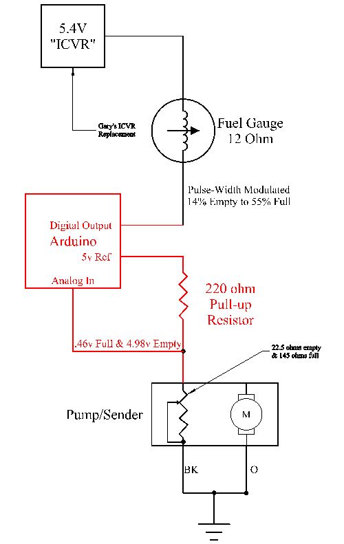
I'm going to document my research here regarding an interface between Bricknose fuel sending units and the Bullnose fuel gauge. And the overall plan is to use an Arduino Uno to do the work. Here's a block diagram, with the things in red being the added parts for the interface:
 Next, here's the logic in doing it: The resistance for the sending unit in the 1990 fuel delivery module I'll be using will be 22.5 ohms when the tank is empty and 145 ohms full - according to the 1996 EVTM. One end of the resistor is tied to ground, so there will have to be a resistor from the 5v supply on the Arduino to the potentiometer/sending unit, meaning the circuit will go from the 5v supply through a resistor and connect there to both the analog input of the Arduino as well as to the potentiometer.
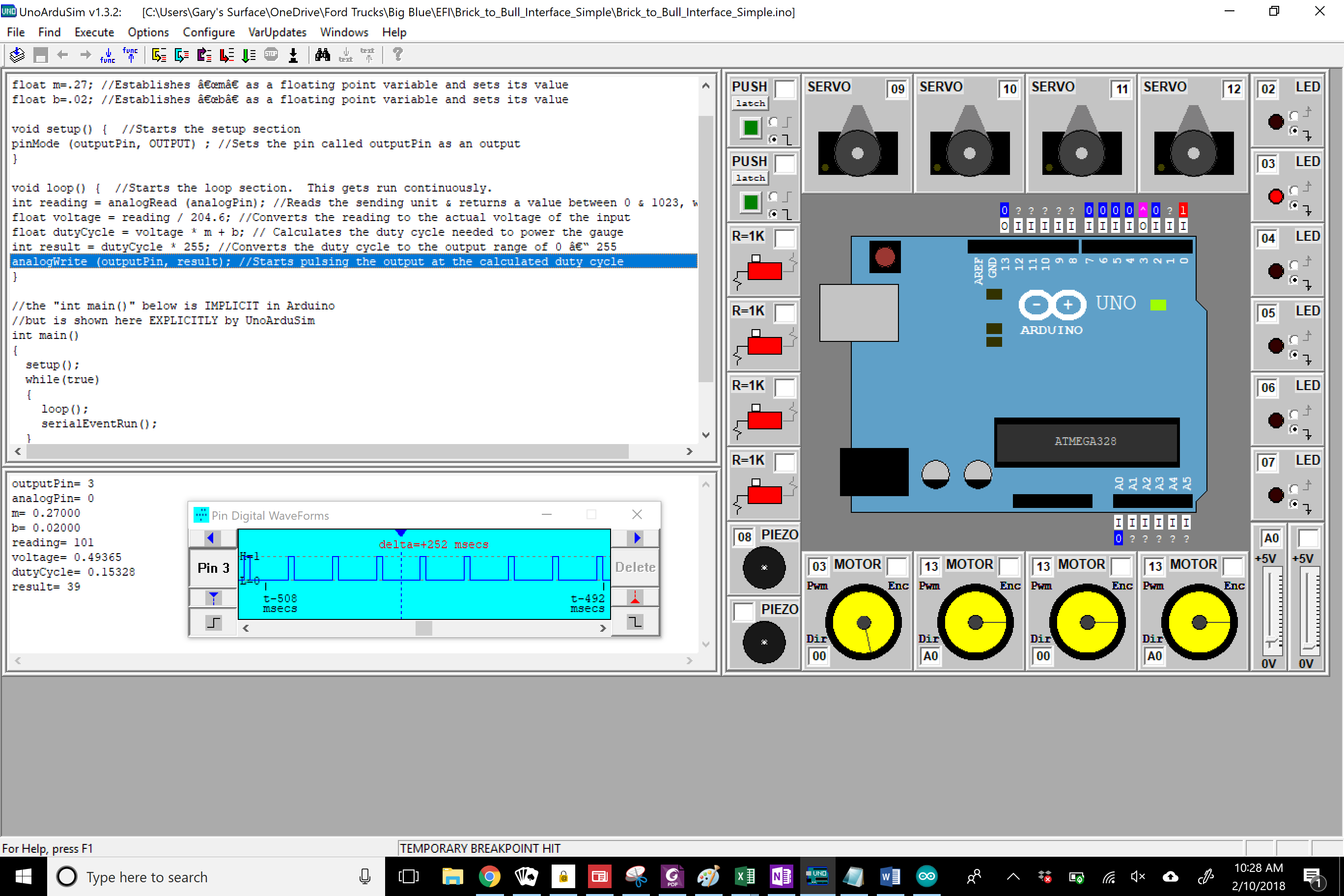
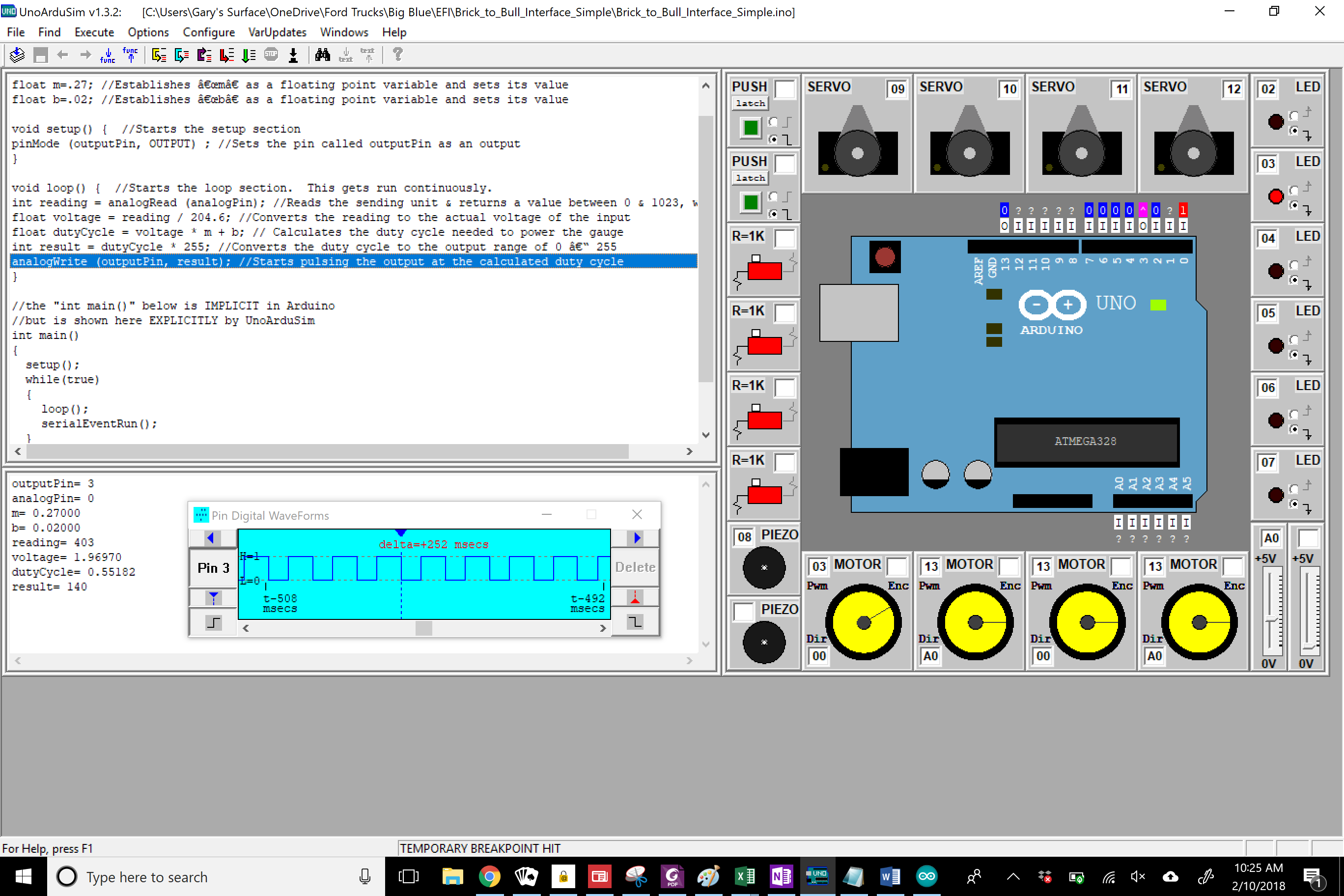
The next step is to write a "sketch" as it is called in Arduino. And here's the basic sketch, although later I'll probably add an I/O routine to allow fine tuning the M and B parameters on the fly: int outputPin = 3; //Establishes an integer variable that is used for the output pin #
|
|
Those Arduinos are neat & cool! I wish we had them when I was first getting into electronics as a 12-13 yo kid... but of course we didn't have peecees and Apple was a fruit, the "portable" computer on which I played Adventure(0) was larger than a suitcase.
~~ That MOSFET Nanoshield thing... shipping to the USA starts at $40? eeeeek. :( ~~ But why, Gary, are you not merely using the correct sending unit? Are there none available anymore? ~~ (0) host% /usr/games/adventure Welcome to Adventure!! Would you like instructions? yes Somewhere nearby is Colossal Cave, where others have found fortunes in treasure and gold, though it is rumored that some who enter are never seen again. Magic is said to work in the cave. I will be your eyes and hands. Direct me with commands of 1 or 2 words. I should warn you that I look at only the first five letters of each word, so you'll have to enter "northeast" as "ne" to distinguish it from "north". (Should you get stuck, type "help" for some general hints. For information on how to end your adventure, etc., type "info".) This program was originally developed by Will Crowther. Most of the features of the current program were added by Don Woods. Address complaints about the UNIX version to Jim Gillogly (jim@rand.org). You are standing at the end of a road before a small brick building. Around you is a forest. A small stream flows out of the building and down a gully. enter You are inside a building, a well house for a large spring. There are some keys on the ground here. There is a shiny brass lamp nearby. There is food here. There is a bottle of water here. get keys OK |
Re: Bricknose Sender to Bullnose Gauge Interface
|
Administrator
|
Chris! Where ya been?
Yes, the Arduinos are neat. I built an 8085-based microcontroller years ago that is far less capable than an Arduino. FAR And I had to write the OS and do all the wiring. As for the shield, that was just an example, and a bad one as it is for a Nano and I'm using an Uno. But there are plenty more - with very little shipping. On the sending unit, you'll need to read the EFI For Big Blue thread to get the whole idea, but I'll summarize. However, first I'm looking for a solution that will be easily maintained by my offspring in the years to come. And that rules out options like piecing things together with a sending unit from here and a pump from there. I want a bolt-in solution. And the options I found were: 1985 460: Most would think the "correct" sender would be for an '85 460, which is what Big Blue is.
|
Re: Bricknose Sender to Bullnose Gauge Interface
|
Administrator
|
This post was updated on .
I'm thinking of more possibilities for the Arduino since it'll have lots of left over computational as well as I/O power. And, here are two ideas:
Bullnose sender to Bricknose gauges: The 1987 EVTM says that the Bricknose senders are 10 ohm for Empty and 210 ohms for Full. But, not knowing what the resistance of the gauge itself might be I've realized I can't calculate the current flow and, therefore, the needed pulse width.Ammeter to Voltmeter: I researched this idea a bit today. The ammeter obviously requires a negative current to show discharge and a positive one to show a charge. I tested one of my ammeters and what it took to swing it full scale was surprising: 0.15v @ .9 amp to go positive, and 0.17v @ 1.0 amp to go negative. I was hoping to drive it directly from the Arduino, but it will require a high-current source like the fuel gauge. And, I don't think it is very feasible.
Gary, AKA "Gary fellow": Profile
Dad's: '81 F150 Ranger XLT 4x4: Down for restomod: Full-roller "stroked 351M" w/Trick Flow heads & intake, EEC-V SEFI/E4OD/3.50 gears w/Kevlar clutches
|
Re: Bricknose Sender to Bullnose Gauge Interface
|
Gary, I've had some success with my analog approach. Possibly some of my findings may apply to an interface with an Arduino solution as well.
I did some testing with a gauge cluster out of my 86. It was working when I dismantled the truck and I did my testing by applying 12.6 VDC to the flasher style IVR. A few notes, I did check the IVR output with a test light and it does flash at about a 1hz rate with a 30 to 40% duty cycle. Peak voltage of course equals applied battery. I tested the high and low limits of the fuel gauge. I found I needed 9 ohms to ground for a full indication and 50 ohms to ground for an empty indication. I was aiming for the exact line. Of course, the gauge will travel past E and F in normal operation. There is a certain amount of settling time required for the gauge to reach a nominal reading. There also seems to be some hysteresis in the needle movement as the settling point may not be exact depending on whether you are increasing, or decreasing the sender resistance, however it is adequate for the purposes of the gauge. The readings are repeatable and do not seem to be affected by small variations in the battery voltage. I tested as low as 11.5 V and as high as 14.6 V with no noticeable effect on the gauge reading. Certainly, there would be a point where calibration would be affected, but for normal operation, it is stable enough. My lack of recent activity in such a project was reflected by a longing for some of the equipment I used to have at my disposal. Got rid of a lot of it when moving 15 years ago. End result was a lot of flying connections, but I was able to prove the concept. Now it's time for the technobabble. Basically, my arrangement is a TIP41C NPN transistor arranged as a collector current sink to ground with a 9 ohm series resistor to the fuel gauge.I have the base snubbed with 1K and a 0.1 mf capacitor to ground and I was able to prove I can drive the fuel gauge accurately with a base current variable between 1 ma empty and 3 ma full. The movement is linear with the current change. I tested this with a potentiometer substituting for the sender and I'm going to try again with an actual FDM. There needs to be a little more development with arranging the fuel sender, but it is simply a voltage divider with a series resistor to the base of the transistor. I will incorporate hi and lo reading adjustments into this part of the circuit to allow for calibration and there would be no need to substitute components for such a purpose. I'm going to make some drawings and a video when I have everything tied up a little better. |
Re: Bricknose Sender to Bullnose Gauge Interface
|
Administrator
|
Ray - This sounds very promising. VERY. But how are you going to accommodate the reversed range of the FDM: 22.5 ohms empty and 145 ohms full? You probably explained, but it went right over my head.
Gary, AKA "Gary fellow": Profile
Dad's: '81 F150 Ranger XLT 4x4: Down for restomod: Full-roller "stroked 351M" w/Trick Flow heads & intake, EEC-V SEFI/E4OD/3.50 gears w/Kevlar clutches
|
Re: Bricknose Sender to Bullnose Gauge Interface
|
Use the sender as the lower leg of a voltage divider. I'm thinking 47 ohm 2 watt series resistor from batt+ to sender. When sender is low, resistance is low and voltage at sender will be low. When sender is high, resistance is high and 47 ohm resistor will pull voltage high. Higher voltage makes higher current into base of transistor, increasing current CE. Lower voltage at empty reduces base current and reduces current CE. 9 ohm resistor is to limit current at full. Sender/voltage divider is quite low source impedence and the drive to the transistor base needs to be 1 to 3 ma. All Ohm's law from there.
Transistors configured like the drawing I put up earlier invert input /output 180 degrees. |
Re: Bricknose Sender to Bullnose Gauge Interface
|
Administrator
|
Perfect! I knew I was missing something and that you were ahead of me.

Gary, AKA "Gary fellow": Profile
Dad's: '81 F150 Ranger XLT 4x4: Down for restomod: Full-roller "stroked 351M" w/Trick Flow heads & intake, EEC-V SEFI/E4OD/3.50 gears w/Kevlar clutches
|
| Edit this page |


